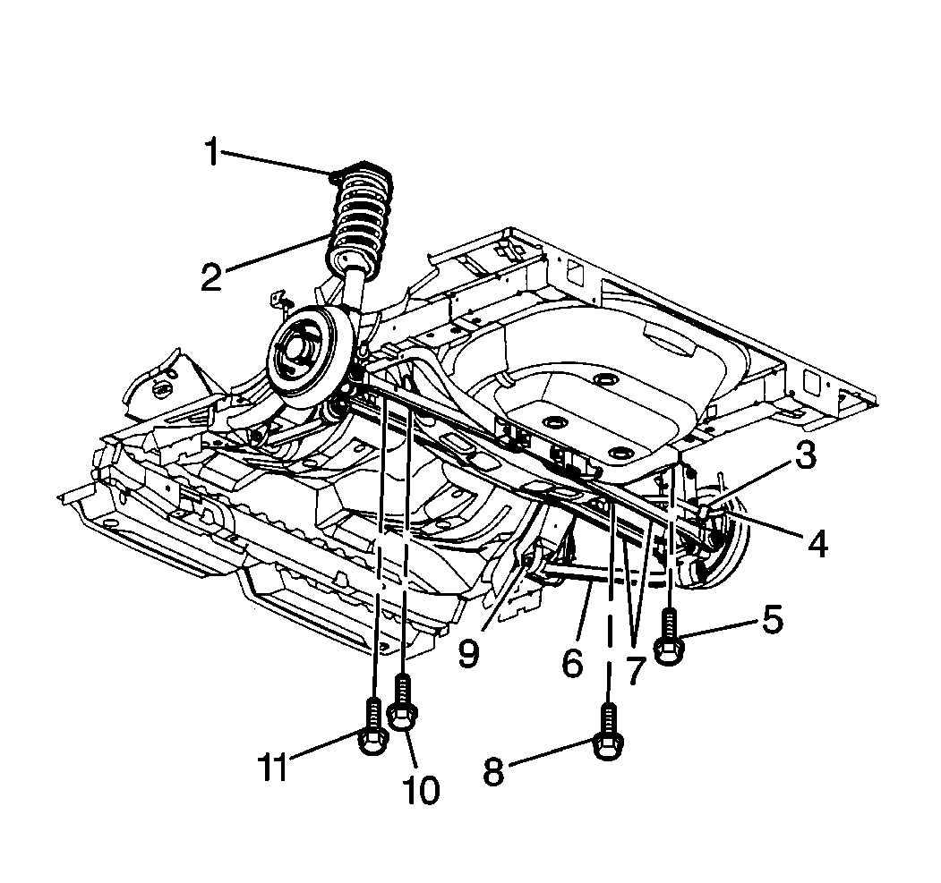
The rear suspension uses coil springs (2) over struts (1), and lightweight aluminum knuckles. Each wheel is mounted to a tri-link independent suspension system. The three links are identified as the inverted U channel trailing arm and the stamped front and rear lateral links (7).
Parallel links allow the rear wheels to deflect rearward when they hit a road hazard, but without moving the toe positive. This suspension system reduces unsprung and overall weight. Handling is improved with the independent action of each rear wheel. The links control lateral wheel deflection.
Several techniques have been employed in order to achieve this independent wheel movement. The tri-link design can be compared to a right angle. The wheel is located at the right angle formed by the lateral links and the trailing arm. The ends of the tri-links are hinged in order to provide vertical wheel travel. The solid links force the wheel to travel through a controlled arc. In this arc the fore-aft position is determined by the trailing arm and the lateral position is determined by the lateral links.
Knuckle Description
The knuckle is a machined aluminum casting. Do not use a hammer in order to loosen suspension components attached to the knuckle. Do not pry or hammer on the aluminum knuckle in any way. Following these instructions will avoid damage to parts and systems.
The suspension performs the following functions:
- Maintaining geometric wheel location
- The knuckle supports the brake drum
- All brake torque and braking forces are transmitted through the tri-links and the strut
- The links maintain the camber angle of the wheel throughout the wheels travel
The links allow for setting toe. The overall result of this rear suspension geometry is to maintain the rear wheels in a near vertical position at all times.
Stabilizer Shaft Description
The stabilizer shaft is attached to the stabilizer link and extends forward. The stabilizer shaft is then connected to the rear suspension support by two rubber bushings and mounting brackets.
Stabilizer Shaft Description
The stabilizer shaft is attached to the stabilizer link and extends forward. The stabilizer shaft is then connected to the rear suspension support by two rubber bushings and mounting brackets.
Hub and Bearing Description
A non-serviceable unit hub and bearing is bolted to the knuckle. This hub and bearing is a sealed, maintenance free unit.
Struts Description
The suspension system should be periodically inspected for the following conditions:
- Shock absorbency
- Bushing durability
- Tightness of attaching bolts
- Any visible damage
- Misalignment
- Excessive wear
