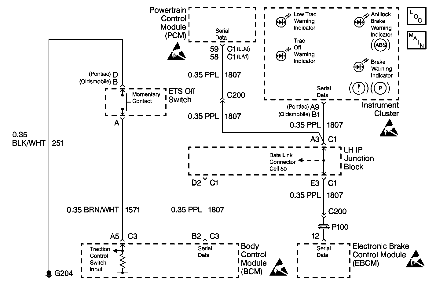
Circuit Description
Four-way serial communication is sent back and forth between the EBCM, IPC, PCM, and the BCM. A message from the IPC is sent to the BCM within seven seconds after ABS initialization. A serial communication failure does not allow the proper warning indicator commands to be sent back to the IPC.
Diagnostic Aids
The ETS OFF indicator will be ON and the Enhanced Traction System will be disabled whenever the scan tool is connected to the DLC with the ignition switch is in the ON position.
Use the Lamp Test function of the Scan Tool in order to turn the indicator ON while looking for an intermittent malfunction in the ETS OFF warning indicator circuitry.
Thoroughly inspect any circuitry that may cause the intermittent complaint for the following conditions:
| • | Backed out terminals |
| • | Improper mating |
| • | Broken locks |
| • | Improperly formed or damaged terminals |
| • | Poor terminal-to-wiring connections |
| • | Physical damage to the wiring harness |
Test Description
-
This test determines if a Powertrain malfunction has turned the ETS Off indicator ON.
-
This test determines if the malfunction is caused by the IPC.
-
This test checks for an ETS Off switch stuck in the closed position.
-
This test checks for a short to ground in the switched input to the BCM.
Step | Action | Value(s) | Yes | No | ||||||||||
|---|---|---|---|---|---|---|---|---|---|---|---|---|---|---|
|
Important: Zero the J 39200 test leads before making any resistance measurements. Refer to the J 39200 user's manual. | ||||||||||||||
1 | Was the ABS Diagnostic System Check performed? | -- | Go to Step 2 | |||||||||||
Are there any PCM DTCs? | -- | Go to Powertrain On Board Diagnostic (OBD) System Check in Engine Controls - 2.4L or Powertrain On Board Diagnostic (OBD) System Check in Engine Controls - 3.4L | Go to Step 3 | |||||||||||
Did the warning indicators turn OFF? | -- | Go to Step 4 | Go to Diagnostic System Check - Instrument Cluster in Instrument Panel, Gages and Console | |||||||||||
Disconnect the ETS Off switch connector. Does the ETS Off indicator turn OFF? | -- | Go to Step 7 | Go to Step 5 | |||||||||||
Is the resistance within the specified range? | OL (Infinite) | Go to Step 6 | Go to Step 8 | |||||||||||
6 |
Are there signs of poor terminal contact, corrosion or damaged terminals? | -- | Go to Step 9 | Go to Step 10 | ||||||||||
7 | Replace the ETS Off switch. Is the repair complete? | -- | -- | |||||||||||
8 | Repair short to ground in CKT 1571. Is the repair complete? | -- | -- | |||||||||||
9 | Replace all of the terminals or connectors that exhibit signs of poor terminal contact, corrosion or damaged terminal(s). Is the repair complete? | -- | -- | |||||||||||
10 | Replace the BCM. Is the repair complete? | -- | -- | |||||||||||
