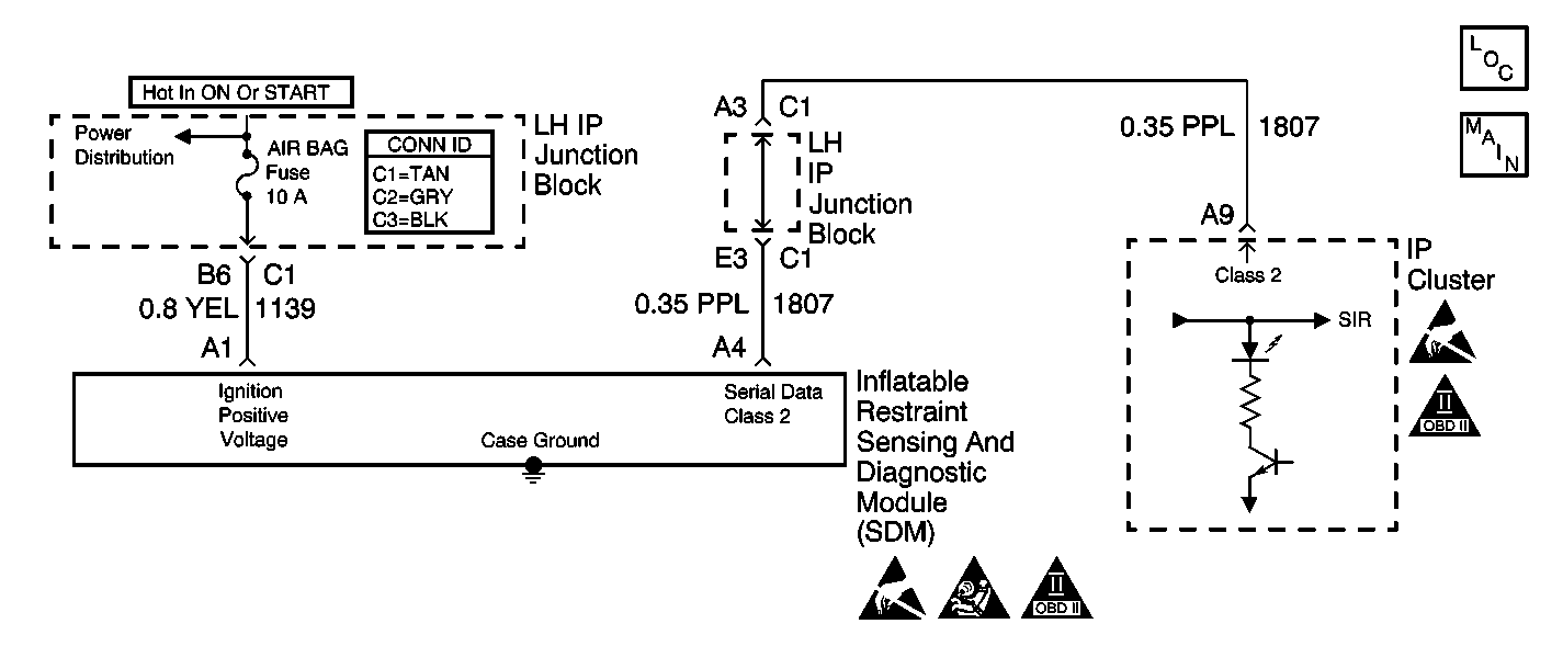
Circuit Description
The ignition switch supplies ignition voltage to the inflatable restraint sensing and diagnostic module (SDM) at terminal A1 using the AIR BAG Fuse. The ignition switch also supplies ignition voltage to the instrument cluster. The AIR BAG warning lamp is controlled by the SDM via Class 2 serial data. When the ignition switch is first turned ON, the instrument cluster flashes the AIR BAG warning lamp seven times. During this time the SDM performs tests on the SIR system then commands the instrument cluster to turn OFF the AIR BAG warning lamp after it has flashed seven times. If the ignition voltage is outside of the normal operating voltage range (9-16 V), the SDM will command the instrument cluster to turn ON the AIR BAG warning lamp with no DTCs present.
Diagnostic Aids
The loss of serial data communication between the SDM and the instrument cluster will cause the AIR BAG warning lamp to come ON solid. Refer to A Diagnostic System Check - Data Link Communications in Data Link Communications.
Test Description
The number(s) below refer to the step number(s) on the diagnostic table.
-
This step checks to see if the AIR BAG warning lamp flashes seven times when the ignition is turned ON.
-
This step checks to see if the scan tool can communicate with the IPC.
-
This step checks to see if battery voltage is being supplied to the SDM.
-
This step checks to see if the SDM connector shows any signs of corrosion, terminal damage, or poor connection.
-
This step checks to see if there is an open or high resistance in the voltage feed circuit to the SDM.
-
This step checks to see if there is an open or high resistance in the voltage feed circuit to the SDM Fuse.
-
This step checks to see that the SDM is properly grounded.
Step | Action | Value(s) | Yes | No |
|---|---|---|---|---|
1 | Did you perform the SIR Diagnostic System Check? | -- | Go to Step 2 | |
Note the AIR BAG warning lamp while turning ON the ignition. Does the AIR BAG warning lamp flash seven times? | -- | Go to Step 4 | Go to Step 3 | |
3 | Replace the instrument cluster. Refer to Instrument Cluster Replacement in Instrument Panel, Gauges and Console. Did you complete the repair? | -- | Go to Step 10 | -- |
Can communication with the IPC be established? | -- | Go to Step 5 | ||
Use the scan tool to request the SIR data list display. Is the ignition voltage displayed on the scan tool within the specified range? | Battery voltage | Go to Step 9 | Go to Step 6 | |
6 | Inspect and repair the ignition voltage feed circuit for an open or high resistance. Did you find and correct the condition? | -- | Go to Step 10 | Go to Step 7 |
Does the resistance measure less than the specified value? | 2 ohms | Go to Step 9 | Go to Step 8 | |
8 | Ensure that the SDM is properly mounted and there is no corrosion on the mounting surface or mounting hardware. Did you complete the action? | -- | Go to Step 10 | -- |
9 | Replace the SDM. Refer to Inflatable Restraint Sensing and Diagnostic Module Replacement . Did you complete the repair? | -- | Go to Step 10 | -- |
10 |
Did you complete the action? | -- | -- |
