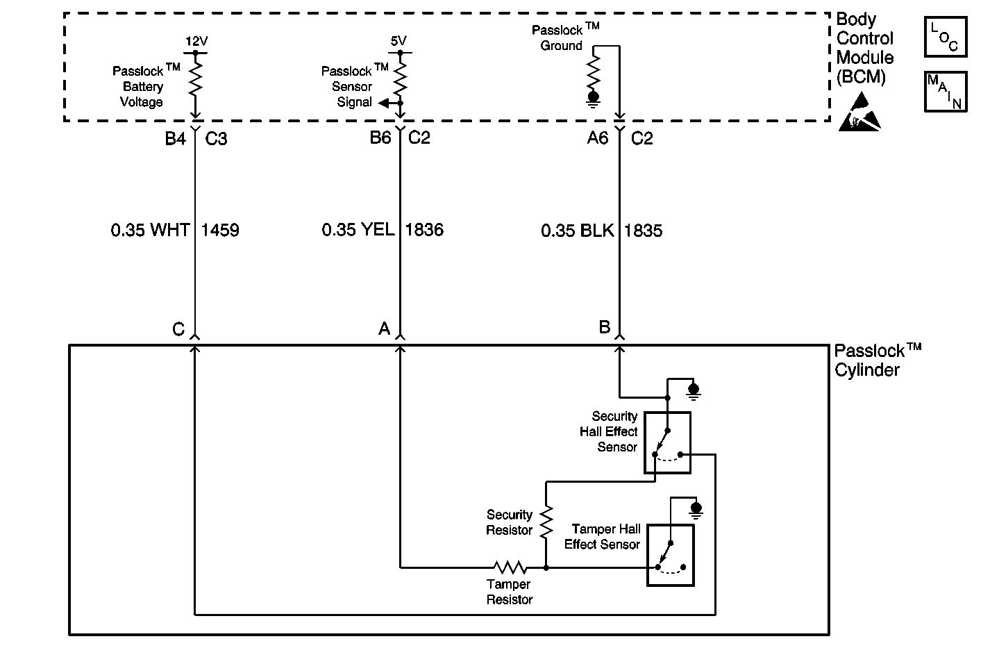
Circuit Description
In this mode, the body control module (BCM) will learn the current Passlock™ sensor code value.
Conditions for Running the DTC
The ignition switch is cycled to CRANK and released to ON.
Conditions for Setting the DTC
| • | A new BCM has been installed and the ignition is turned to the ON position but not rotated to the CRANK position. Once the ignition switch has been rotated to the CRANK position, the BCM will learn the Passlock code. The theft relearn procedure will need to be run in order to make the powertrain control module (PCM) receive the correct fuel enable password. |
| • | The BCM is in the learn mode but does not see a valid Passlock™ sensor code because of a sensor or wiring problem. |
Action Taken When the DTC Sets
| • | The vehicle will not start. |
| • | The SECURITY indicator illuminates. |
Conditions for Clearing the DTC
| • | The BCM is programmed and learns the correct ignition cylinder key code. |
| • | Current DTCs will clear after one ignition cycle if the malfunction is no longer present. |
| • | All of the BCM history codes will be cleared after 100 ignition cycles (from OFF to ON) with no current codes active during the 100 ignition cycles. |
Diagnostic Aids
If the DTC is a history DTC, the problem may be intermittent. Perform the tests shown while wiggling the wiring and connectors. This will often cause the malfunction to appear.
Test Description
The numbers below refer to the step numbers on the diagnostic table.
Step | Action | Yes | No |
|---|---|---|---|
1 | Was the Theft Deterrent Diagnostic System Check performed? | Go to Step 2 | |
2 |
Does the scan tool display DTC B3031 as a current DTC? | Go to Step 3 | Go to Testing for Intermittent Conditions and Poor Connections in Wiring Systems |
Does the scan tool display DTC B2947, B2948, B2957, or B2958? | Go to Step 6 | ||
4 | Inspect for poor connections at the BCM. Refer to Testing for Intermittent Conditions and Poor Connections and Connector Repairs in Wiring Systems. Did you find and correct the condition? | Go to Step 9 | Go to Step 5 |
5 | Replace the BCM. Refer to Body Control Module Replacement in Body Control System. Important: Perform the setup procedure for the body control module. Refer to Body Control Module (BCM) Programming/RPO Configuration . Did you complete the replacement? | Go to Step 9 | -- |
6 | Inspect for poor connections at the Passlock ™ sensor. Refer to Testing for Intermittent Conditions and Poor Connections and Connector Repairs in Wiring Systems. Did you find and correct the condition? | Go to Step 9 | Go to Step 7 |
7 | Replace the Passlock™ sensor. Important: Perform the relearn procedure for the Passlock™ sensor. Refer to PASSLOCK Reprogramming Auto Learn . Did you complete the replacement? | Go to Step 8 | -- |
8 | Perform the Passlock™ learn procedure. Refer to PASSLOCK Reprogramming Auto Learn . Is the repair complete? | Go to Step 9 | -- |
9 |
Does the DTC reset? | Go to Step 4 | System OK |
