For 1990-2009 cars only
Removal Procedure
- Remove the rear suspension support assembly. Refer to Support Replacement .
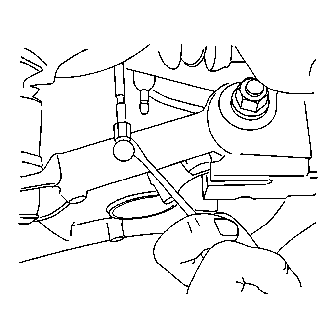
- Remove the electronic level control height sensor link from left control arm.
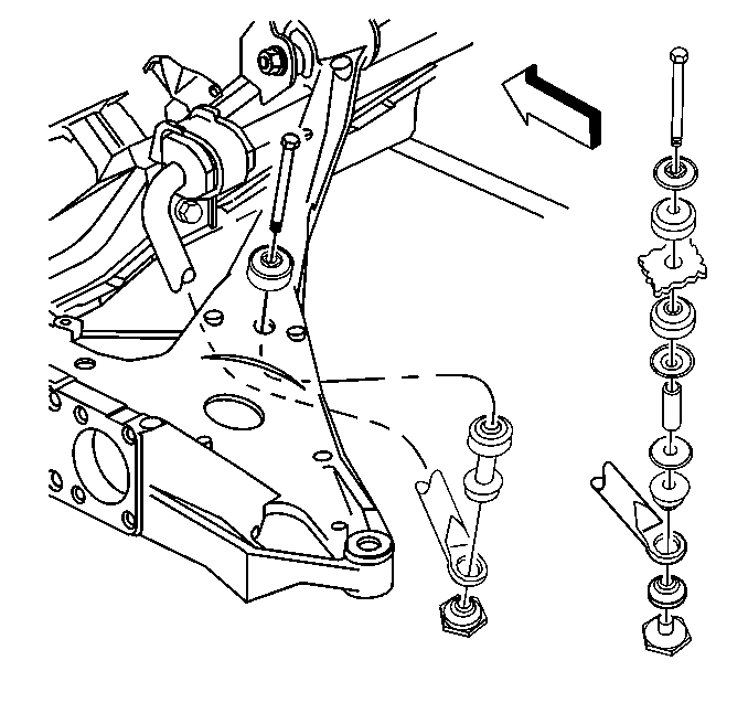
- Remove the stabilizer link bolt.
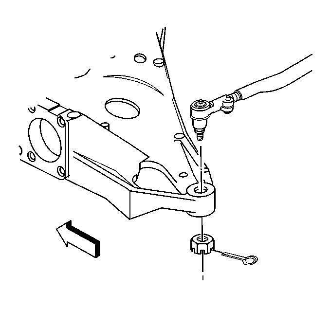
- Remove the tie rod Outer Adjustment Link Replacement .
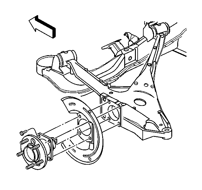
- Remove the hub and bearing, if necessary. Refer to Rear Wheel Bearing and Hub Replacement .
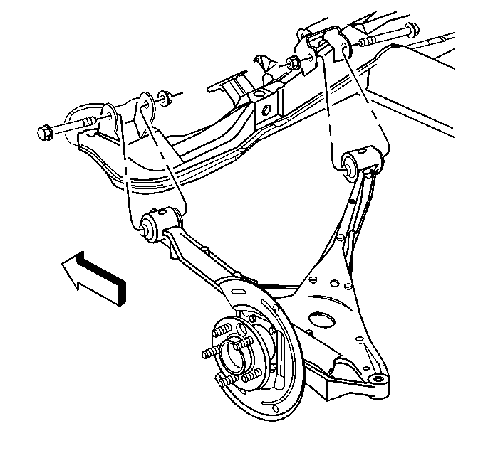
- Remove the nuts and bolts securing the control arm to the rear suspension support assembly.
- Remove the control arm.
Installation Procedure
- Install the control arm to the rear suspension support assembly.
- Install the bolts and nuts.
- Install the hub and bearing if necessary. Refer to Rear Wheel Bearing and Hub Replacement .
- Install the tie rod. Outer Adjustment Link Replacement .
- Connect the ABS electrical connector.
- Install the stabilizer link bolt and nut.
- Install the electronic level control height sensor link on left control arm.
- Install the rear suspension support assembly. Refer to Support Replacement .
- Lower the vehicle to obtain trim height.
- Tighten the control arm nuts.

Important: The control arm nuts should be tightened with the vehicle unsupported and resting on the wheels at the normal trim height.


Tighten
Tighten the stabilizer link bolt nut to 15 N·m (11 lb ft).

Tighten
Tighten the control arm nuts to 106 N·m (78 lb ft).
