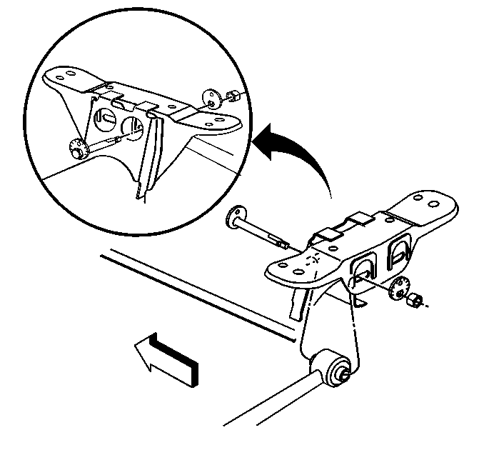
Removal Procedure
- Raise the vehicle.
- Remove the wheel and the tire. Refer to Wheel Removal in Wheels and Tires.
- Loosen the pinch bolt on the outer adjustment link.
- Use a block of wood at least seven inches long in order to support the following components:
- Remove the four exhaust hangers.
- Remove the two rear assembly bolts. Lower the support and the exhaust together.
- Remove the cam bolt and nut. Remove the adjustment link from the support assembly.
- Remove the inner adjustment link from the outer adjustment link noting the turns necessary for reassembly.
Caution: To avoid any vehicle damage, serious personal injury or death when major components are removed from the vehicle and the vehicle is supported by a hoist, support the vehicle with jack stands at the opposite end from which the components are being removed and strap the vehicle to the hoist.
| • | The exhaust |
| • | The rear of the support assembly |

Installation Procedure
- Install the inner adjustment link to the outer adjustment link.
- Install the inner adjustment link to the support assembly.
- Install the following components:
- Raise the support assembly and the exhaust.
- Install the two bolts that secure the support assembly to the body of the vehicle.
- Install the four exhaust hangers.
- Install the tires and the wheels. Refer to Wheel Installation .
- Lower the vehicle.
- Inspect and set the rear toe after installing the adjustment link. Refer to Wheel Alignment Specifications in Suspension.
The number of turns necessary for tightening the link should equal the number of turns necessary for removing the inner adjustment link.

Notice: Use the correct fastener in the correct location. Replacement fasteners must be the correct part number for that application. Fasteners requiring replacement or fasteners requiring the use of thread locking compound or sealant are identified in the service procedure. Do not use paints, lubricants, or corrosion inhibitors on fasteners or fastener joint surfaces unless specified. These coatings affect fastener torque and joint clamping force and may damage the fastener. Use the correct tightening sequence and specifications when installing fasteners in order to avoid damage to parts and systems.
| • | The cam bolt |
Tighten
Tighten the pinch bolt to 48 N·m (35 lb ft).
| • | The washer |
| • | The cam nut |
Tighten
Tighten the cam nut to 75 N·m (55 lb ft).
Tighten
Tighten the bolts to 165 N·m (122 lb ft).
Tighten
Tighten the wheel nuts to 140 N·m (100 lb ft).
