Refer to one of the following Theft Deterrent System schematics:
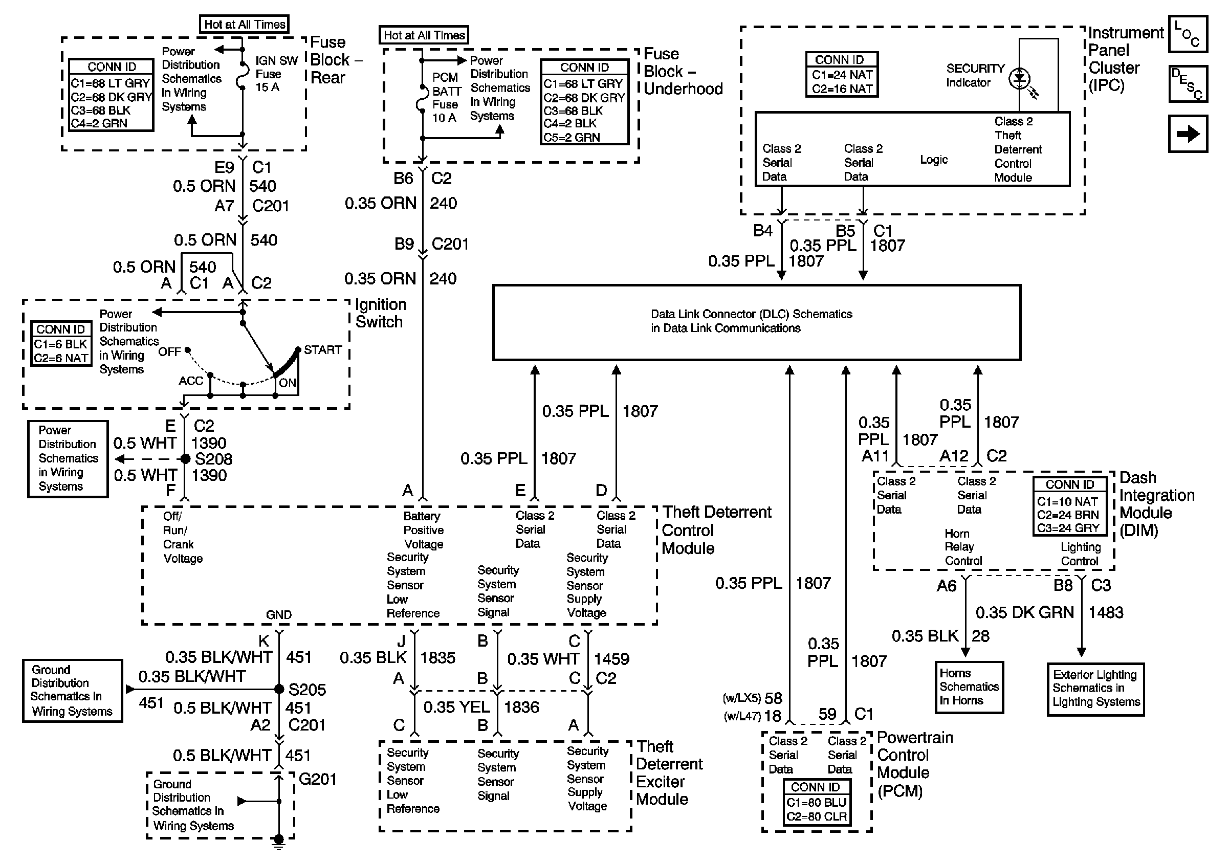
Circuit Description
The theft deterrent controller module checks the theft deterrent exciter module supply circuit for a constant voltage condition.
Conditions for Running the DTC
The theft deterrent controller module must see the ignition switch input. The VTD controller module can not have DTC B1327 set as a current DTC.
Conditions for Setting the DTC
The theft deterrent controller module requires 1 second to monitor the ignition key. After the first second, the theft deterrent controller module turns off the power to the theft deterrent exciter module. If the theft deterrent controller module senses the supply to the theft deterrent exciter module is 12 V for 1 second, the theft deterrent controller module sets this DTC.
Action Taken When the DTC Sets
The theft deterrent controller module will "fail enable" the VTD system and allow the vehicle to start. The theft deterrent controller module will illuminate the security indicator.
Conditions for Clearing the MIL/DTC
The theft deterrent controller module clears the current status of the DTC when it does not sense a 12 V condition on the theft deterrent exciter module supply circuit. The DTC will still be retrieved as current until the ignition switch is cycled. The DTC will become a history DTC at that time.
Diagnostic Aids
Refer to Testing for Intermittent Conditions and Poor Connections and Testing for Electrical Intermittents in Wiring Systems.
Test Description
The numbers below refer to the step numbers on the diagnostic table.
-
Be sure that the original ignition key issued with the vehicle is used when performing the Vehicle Theft Deterrent Diagnostic System Check.
-
Make sure the good ground used is separate from the grounds used by the vehicle theft deterrent module. Voltage measurement must not interfere with possible isolated module ground.
Step | Action | Value(s) | Yes | No |
|---|---|---|---|---|
1 | Did you perform A Diagnostic System Check - Theft Deterrent ? | -- | ||
Does the voltage measure near the specified value? | 12 V | |||
3 | Test the security system sensor supply circuit for a short to voltage. Refer to Circuit Testing in Wiring Systems. Did you find and correct the condition? | -- | ||
4 | Inspect for poor connections/terminal tension at the theft deterrent exciter module harness connector. Refer to Testing for Intermittent Conditions and Poor Connections and Connector Repairs in Wiring Systems. Did you find and correct the condition? | -- | ||
5 | Inspect for poor connections/terminal tension at the vehicle theft deterrent (VTD) controller module harness connector. Refer to Testing for Intermittent Conditions and Poor Connections and Connector Repairs in Wiring Systems . Did you find and correct the condition? | -- | ||
6 | Replace the theft deterrent exciter module . Refer to Theft Deterrent Exciter Module Replacement . Did you complete the replacement? | -- | -- | |
7 |
Important: Perform the vehicle theft deterrent controller module set up procedure. Replace the VTD controller module. Refer to Vehicle Theft Deterrent (VTD) Controller Module Replacement . Did you complete the replacement? | -- | -- | |
8 | Clear the diagnostic trouble codes. Operate the vehicle within the Conditions for Running the DTC as specified in the supporting text. Does the DTC reset? | -- | System OK |
