GM Service Manual Online
For 1990-2009 cars only
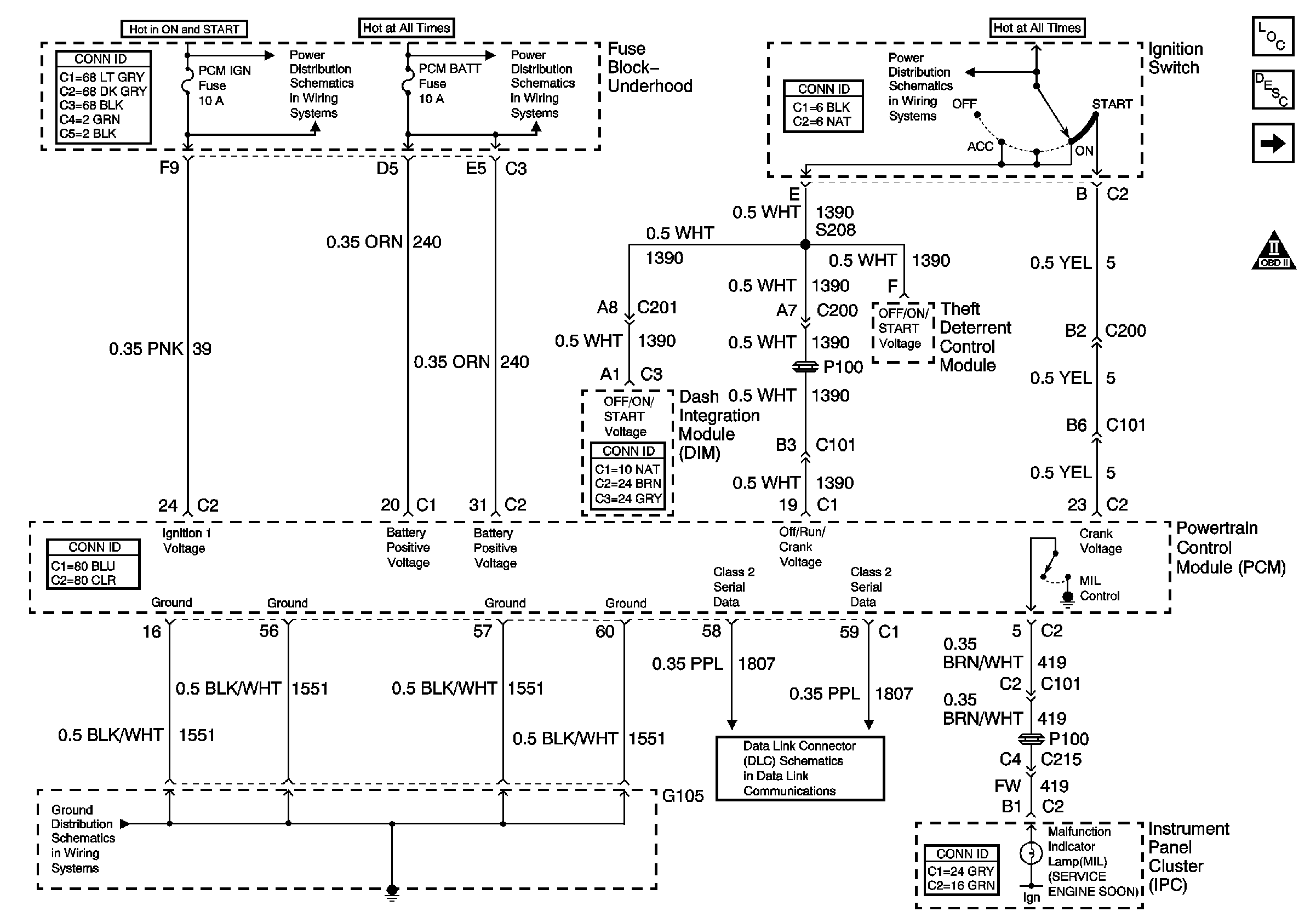
Figure 1:

Ignition Switch and Controls


Object Number: 397415  Size: FS
Master Electrical Component List
Powertrain Control Module Description
Ignition Control Modules
OBD II Symbol Description Notice
IGN SW Fuse (Fuse Block-Rear)
Battery Feed to the Fuse Block-Underhood
G104 and G105, LX5
Serial Data Class 2
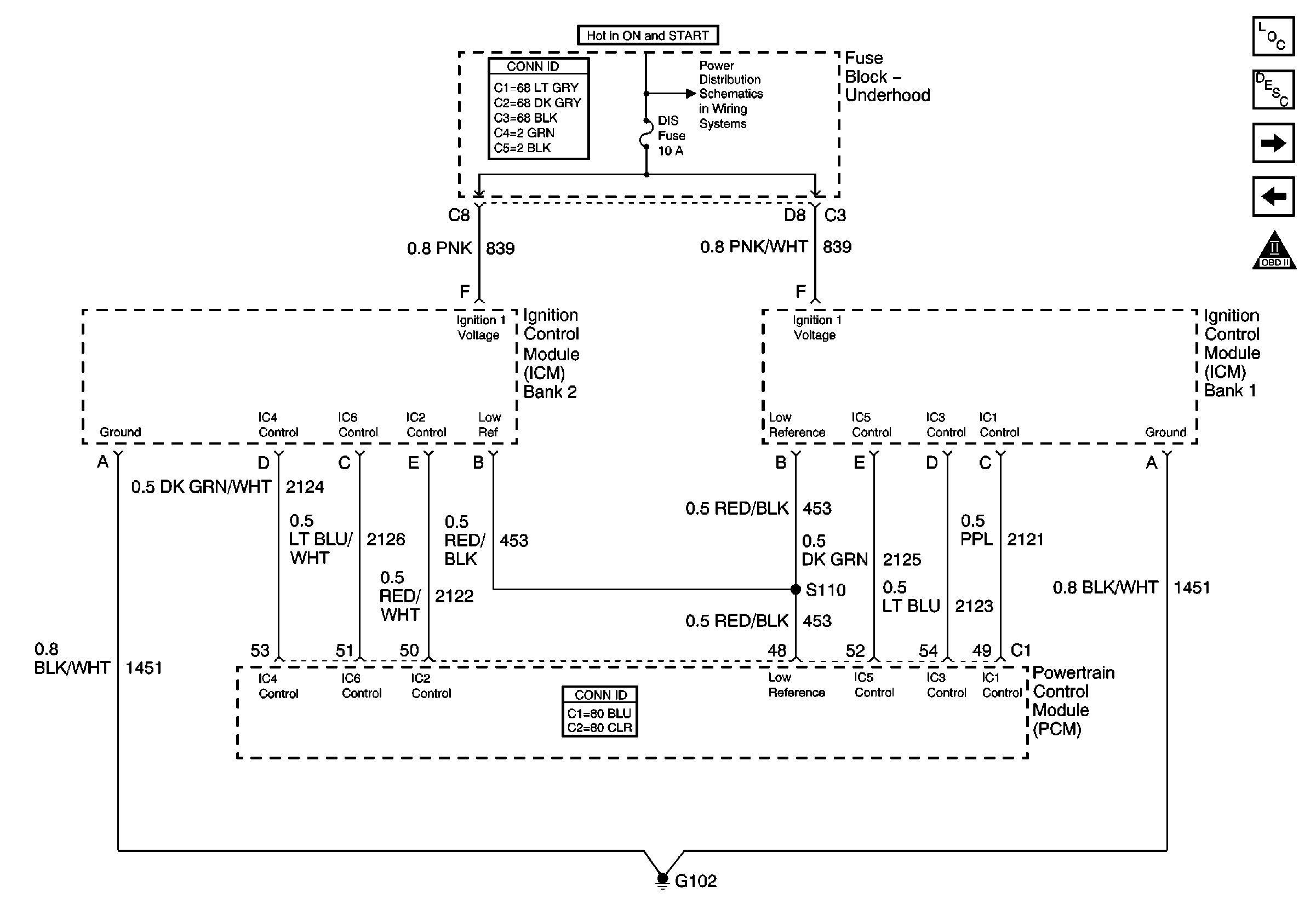
Figure 2:

Igntion Control Modules


Object Number: 397418  Size: FS
Master Electrical Component List
Electronic Ignition (EI) System Description
Camshaft and Crankshaft Position Sensors, TCC/Cruise Release Switch
Ignition Switch and Controls
OBD II Symbol Description Notice
Battery Feed to the Fuse Block-Underhood
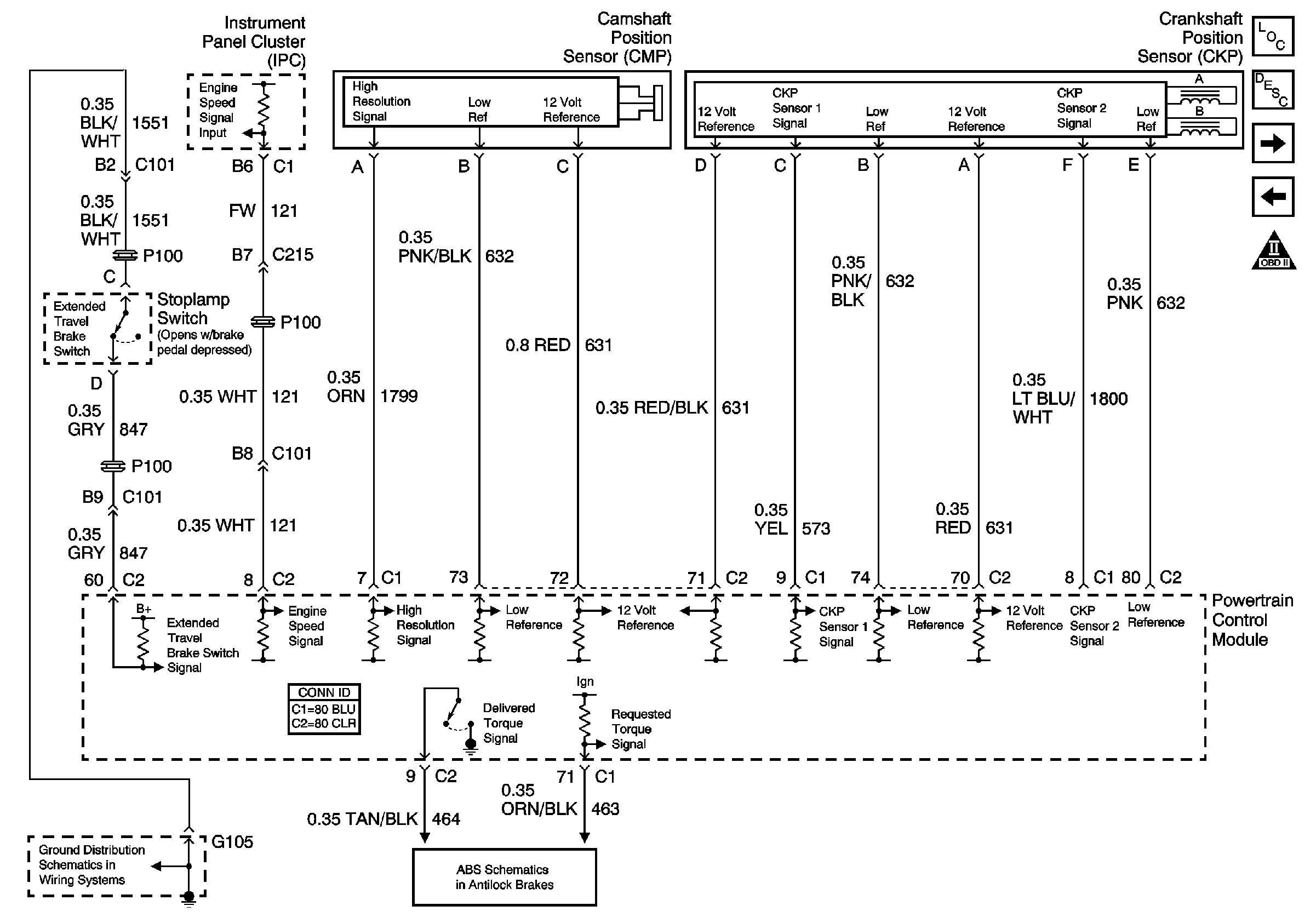
Figure 3:

Camshaft and Crankshaft Position Sensors, TCC/Cruise Release Switch


Object Number: 598321  Size: FS
Master Electrical Component List
Powertrain Control Module Description
Fuel Tank and Sender Assembly and Controls
Ignition Control Modules
OBD II Symbol Description Notice
Traction Control (w/NW9) and Variable Effort Steering (w/NV8)
G104 and G105, LX5
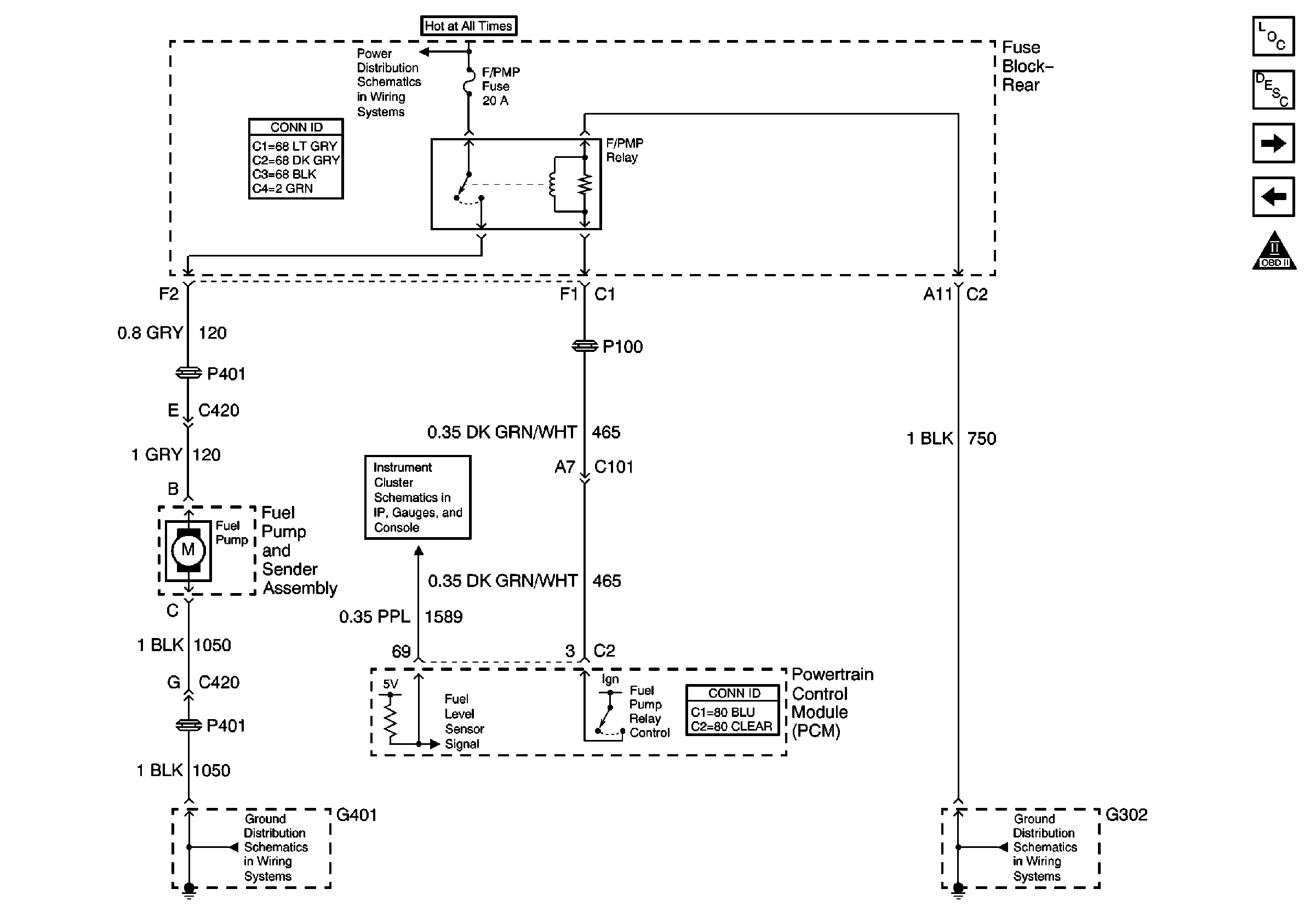
Figure 4:

Fuel Tank and Sender Assembly and Controls


Object Number: 397409  Size: FS
Master Electrical Component List
Fuel System Description
Fuel Injectors
Camshaft and Crankshaft Position Sensors, TCC/Cruise Release Switch
OBD II Symbol Description Notice
G302
G401 (1 of 2)
Battery Feed to the Fuse Block-Rear
Gauges
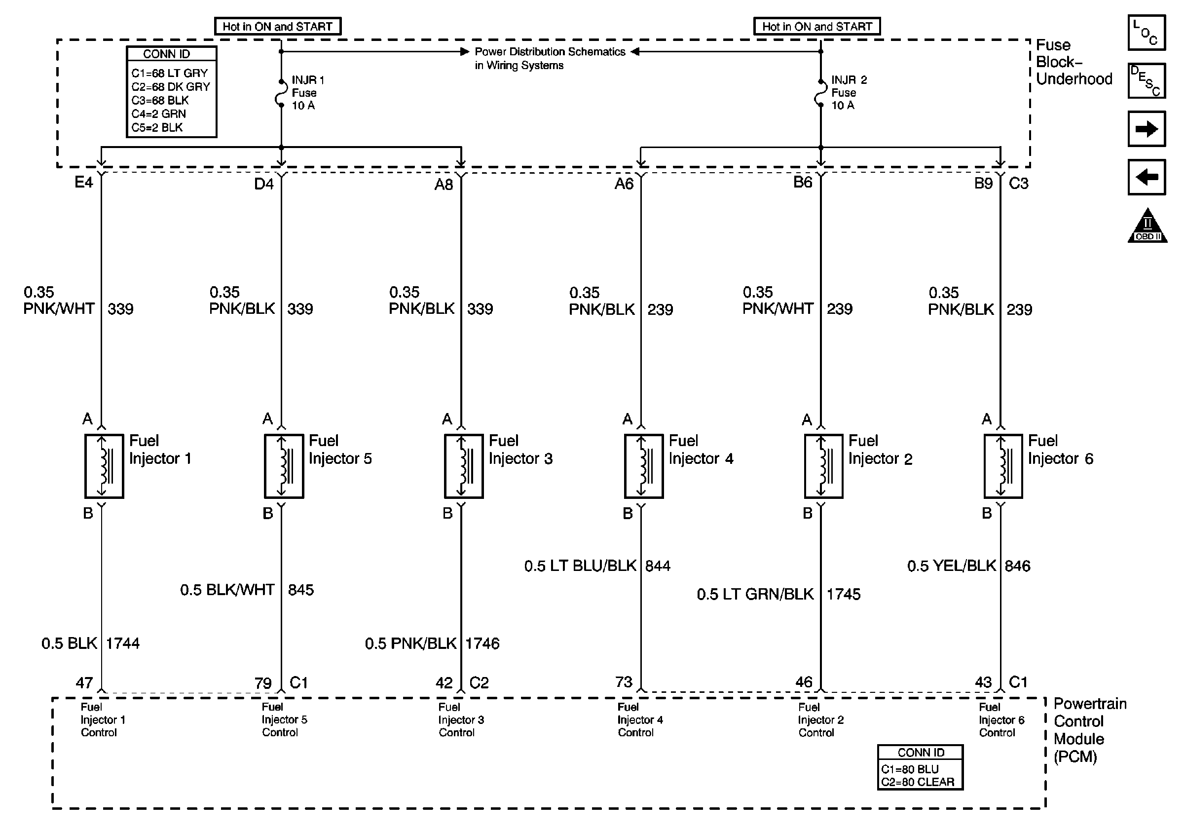
Figure 5:

Fuel Injectors


Object Number: 397406  Size: FS
Master Electrical Component List
Fuel System Description
Sensors
Fuel Tank and Sender Assembly and Controls
OBD II Symbol Description Notice
Battery Feed to the Fuse Block-Underhood
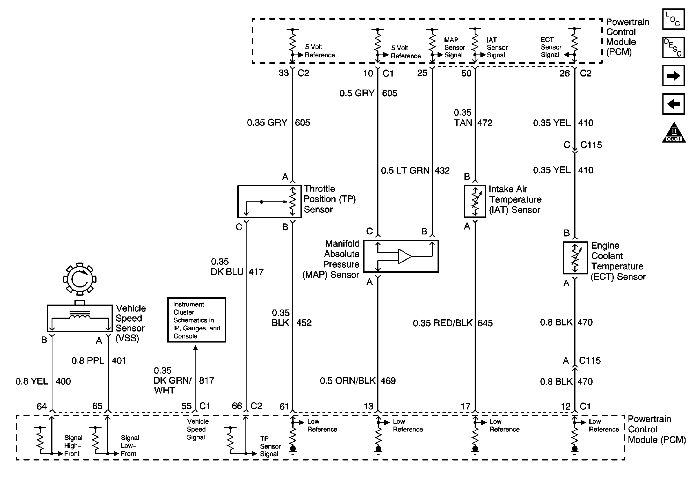
Figure 6:

Sensors


Object Number: 397424  Size: FS
Master Electrical Component List
Powertrain Control Module Description
Fuel Pressure Sensor and EVAP Canister Purge Vent Valve
Fuel Injectors
OBD II Symbol Description Notice
Gauges
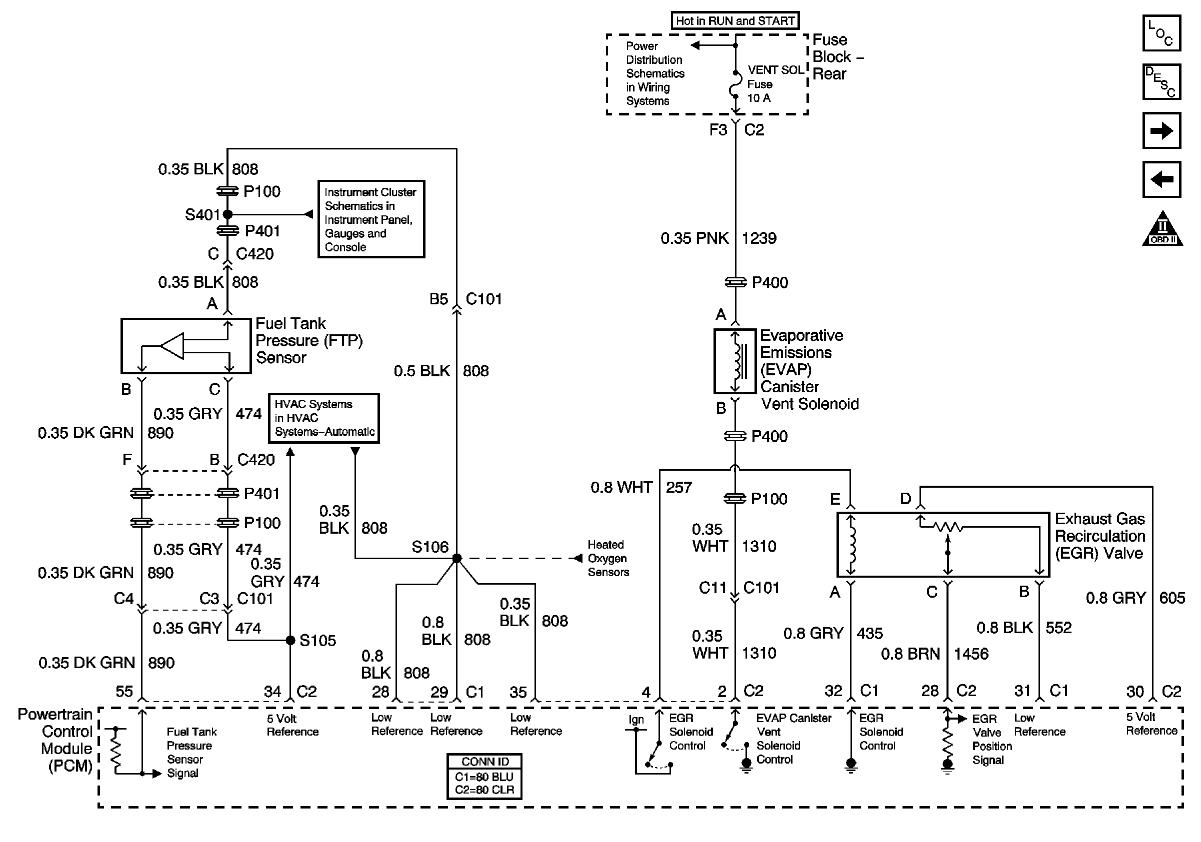
Figure 7:

Fuel Pressure Sensor and EVAP Canister Purge Vent Valve


Object Number: 598327  Size: FS
Master Electrical Component List
Exhaust Gas Recirculation (EGR) System Description
Heated Oxygen Sensors
Sensors
OBD II Symbol Description Notice
Gauges
Compressor Control W/LX5 (V6)
Battery Feed to the Fuse Block-Rear
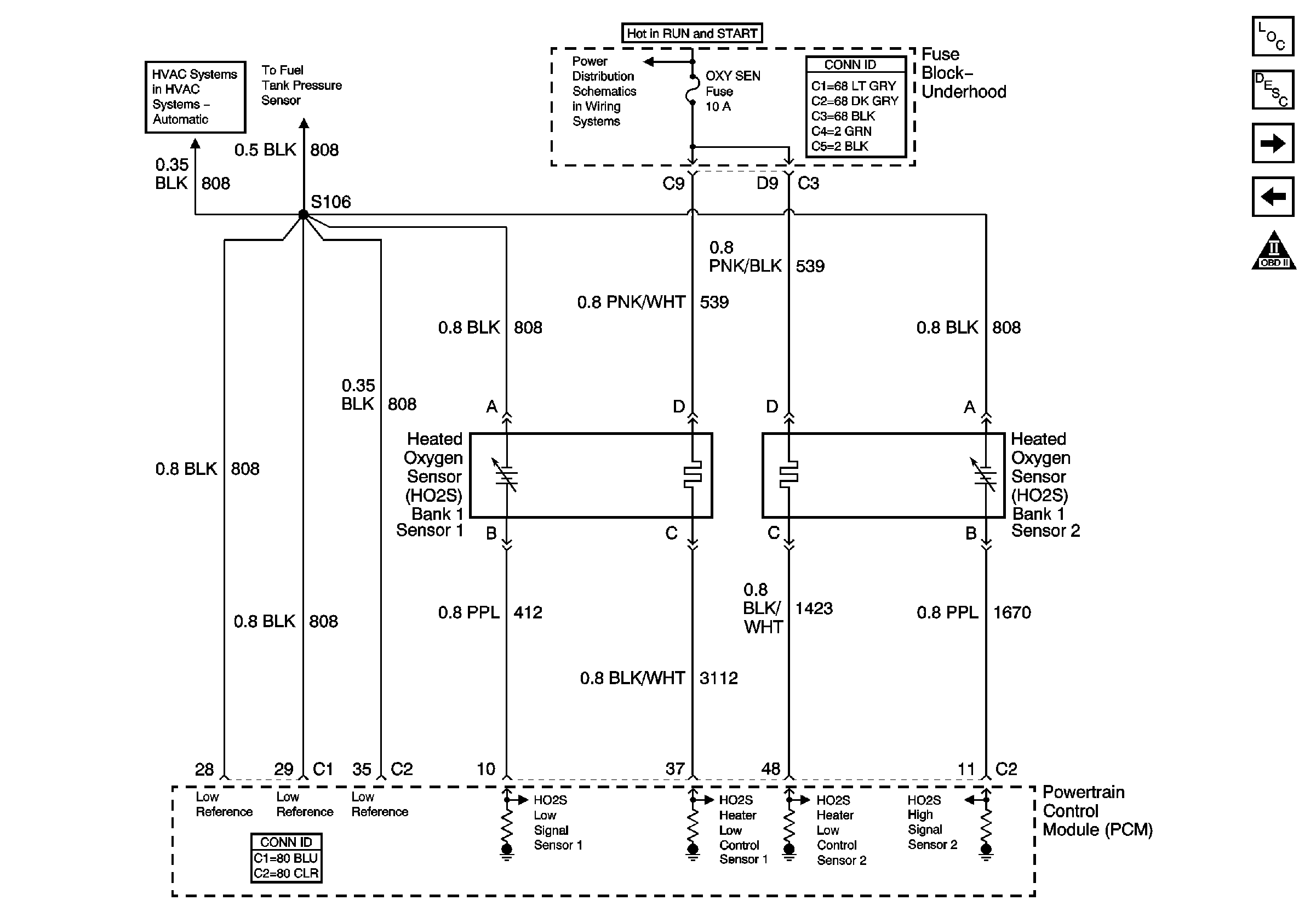
Heated Oxygen Sensors
Figure 8:

Heated Oxygen Sensors


Object Number: 598330  Size: FS
Master Electrical Component List
Air Intake System Description
EVAP Canister Purge Valve, IAC, and MAF
Fuel Pressure Sensor and EVAP Canister Purge Vent Valve
OBD II Symbol Description Notice
Battery Feed to the Fuse Block-Underhood
Fuel Pressure Sensor and EVAP Canister Purge Vent Valve
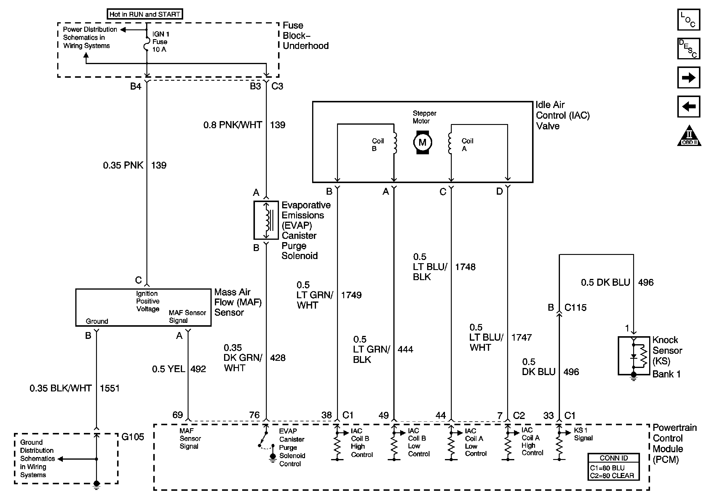
Figure 9:

EVAP Canister Purge Valve, IAC, and MAF


Object Number: 397405  Size: FS
Master Electrical Component List
Air Intake System Description
AIR Pump and Controls
Heated Oxygen Sensors
OBD II Symbol Description Notice
Battery Feed to the Fuse Block-Underhood
G104 and G105, LX5
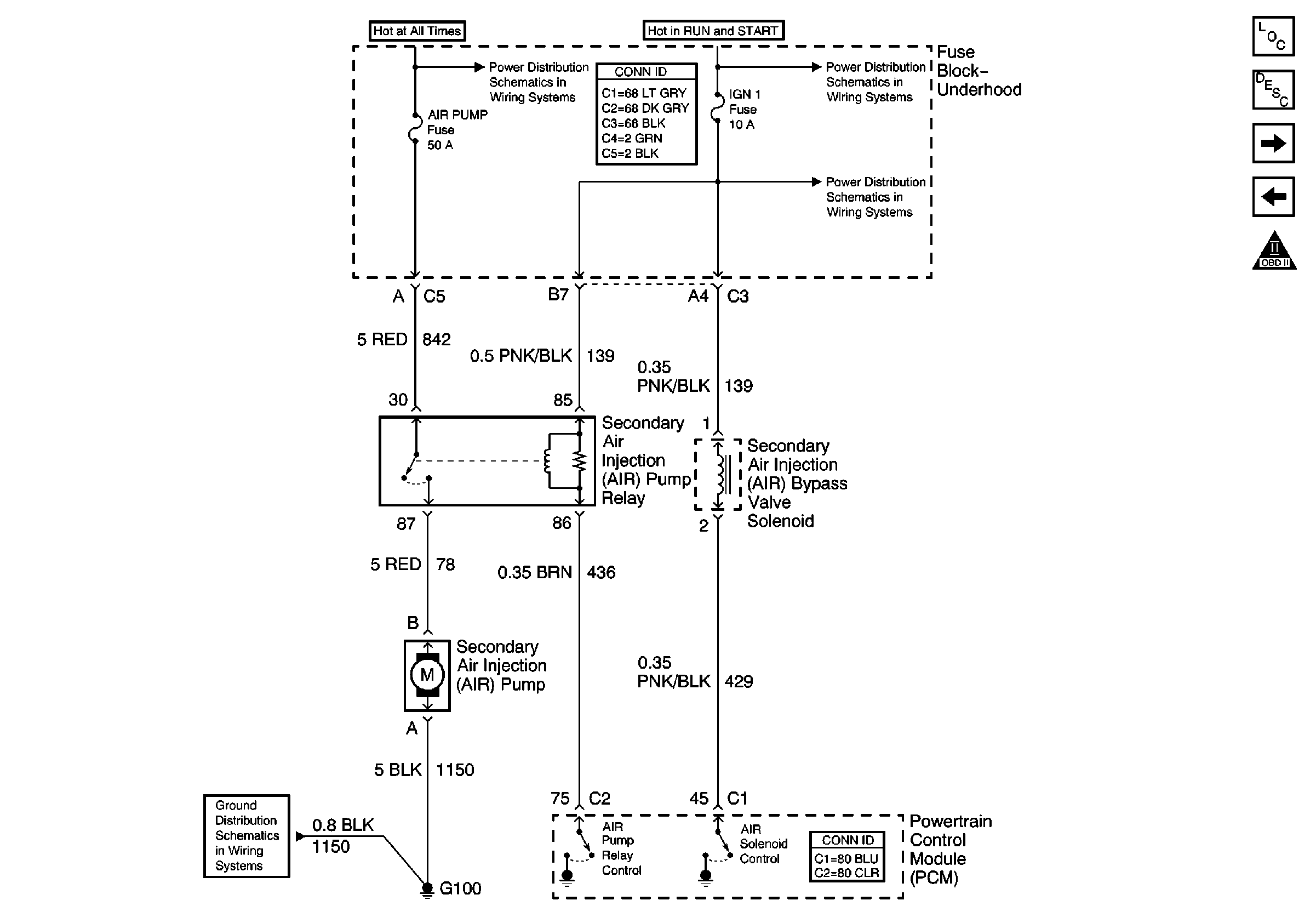
Figure 10:

AIR Pump and Controls


Object Number: 397413  Size: FS
Master Electrical Component List
Secondary Air Injection System Description
PCM Controls (1 of 2)
EVAP Canister Purge Valve, IAC, and MAF
OBD II Symbol Description Notice
G100 and G102, LX5
Battery Feed to the Fuse Block-Underhood
L47 IGN 1, OXY SEN, DIS Fuses and IGN 1 Relay (Fuse Block-Underhood)
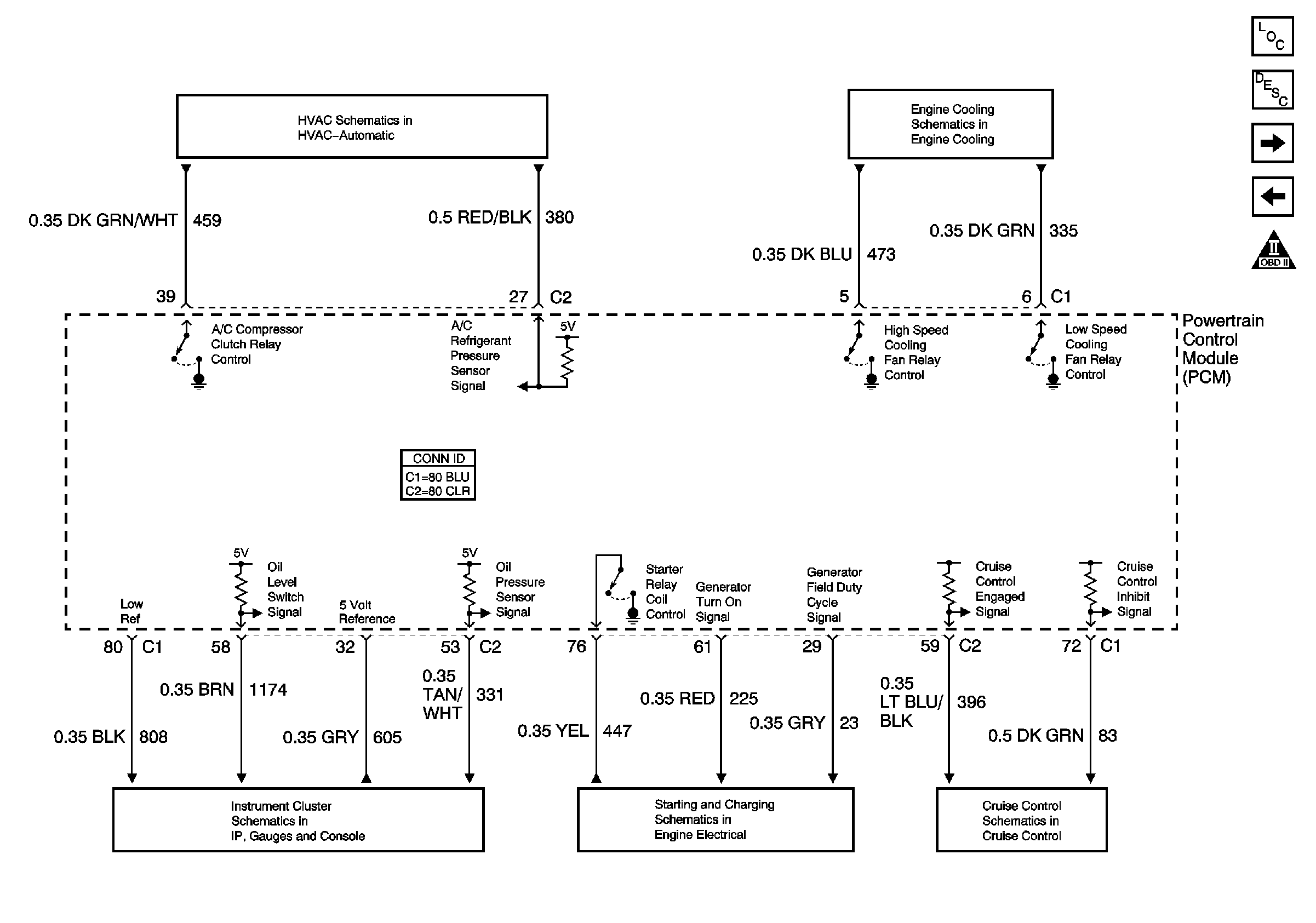
Figure 11:

PCM Controls (1 of 2)


Object Number: 696238  Size: FS
Master Electrical Component List
Powertrain Control Module Description
PCM Controls (2 of 2)
AIR Pump and Controls
OBD II Symbol Description Notice
Cooling Fans and Relays
Compressor Control W/LX5 (V6)
Indicators
Starter Solenoid Controls
CCM, PCM Controls and Vehicle Speed Input
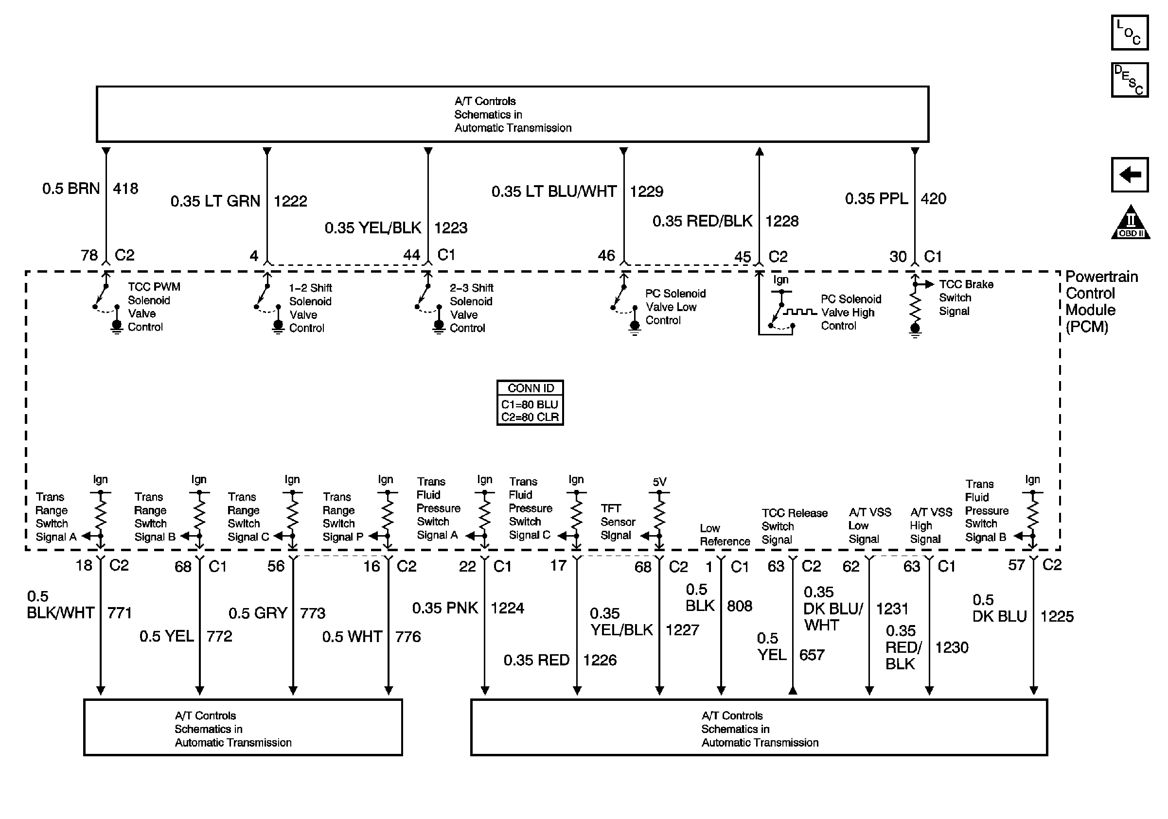
Figure 12:

PCM Controls (2 of 2)


Object Number: 696239  Size: FS
Master Electrical Component List
Powertrain Control Module Description
PCM Controls (1 of 2)
OBD II Symbol Description Notice
Transmission Solenoids
Internal Mode Switch Inputs
Transmission W/LX5