| |||||||
|---|---|---|---|---|---|---|---|
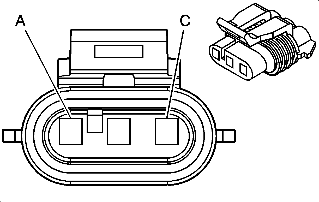
Connector Part Information |
| ||||||
Pin | Wire Color | Circuit No. | Function | ||||
A | ORN | 1799 | High Resolution Signal | ||||
B | PNK/BLK | 632 | Low Reference | ||||
C | RED | 631 | 12 Volt Reference | ||||
| |||||||
|---|---|---|---|---|---|---|---|
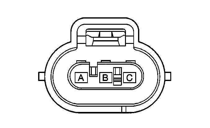
Connector Part Information |
| ||||||
Pin | Wire Color | Circuit No. | Function | ||||
A | LT GRN | 1867 | 12 Volt Reference | ||||
B | YEL/BLK | 1868 | Low Reference | ||||
C | LT BLU/WHT | 1800 | CKP Sensor A Signal | ||||
| |||||||
|---|---|---|---|---|---|---|---|
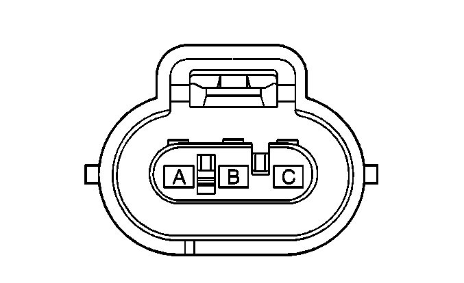
Connector Part Information |
| ||||||
Pin | Wire Color | Circuit No. | Function | ||||
A | LT GRN | 2867 | 12 Volt Reference | ||||
B | YEL | 2868 | Low Reference | ||||
C | YEL | 573 | CKP Sensor B Signal | ||||
| |||||||
|---|---|---|---|---|---|---|---|
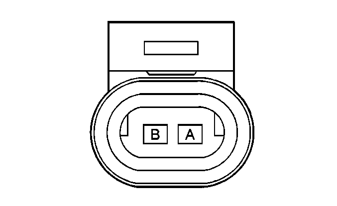
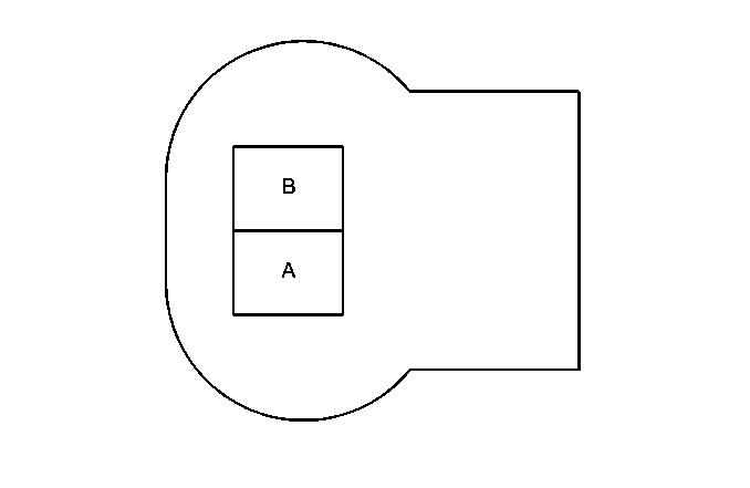
Connector Part Information |
| ||||||
Pin | Wire Color | Circuit No. | Function | ||||
A | BLK | 2761 | Low Reference | ||||
B | YEL | 410 | ECT Sensor Signal | ||||
| |||||||
|---|---|---|---|---|---|---|---|
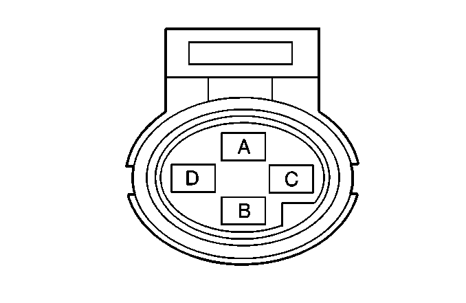
Connector Part Information |
| ||||||
Pin | Wire Color | Circuit No. | Function | ||||
A | BRN | 1174 | Oil Level Switch Signal | ||||
B | BLK/WHT | 1151 | PCM Ground | ||||
| |||||||
|---|---|---|---|---|---|---|---|
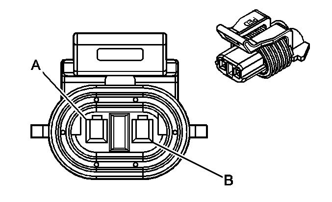
Connector Part Information |
| ||||||
Pin | Wire Color | Circuit No. | Function | ||||
A | BLK | 2755 | PCM Ground | ||||
B | TAN/WHT | 331 | Oil Pressure Sensor Signal | ||||
C-D | -- | -- | Not Used | ||||
| |||||||
|---|---|---|---|---|---|---|---|
Connector Part Information |
| ||||||
Pin | Wire Color | Circuit No. | Function | ||||
A | PNK | 139 | Ignition 1 Voltage | ||||
B | DK GRN/WHT | 428 | EVAP Canister Purge Solenoid Control | ||||

| |||||||
|---|---|---|---|---|---|---|---|
Connector Part Information |
| ||||||
Pin | Wire Color | Circuit No. | Function | ||||
A | PNK | 1239 | Ignition 1 Voltage | ||||
B | WHT | 1310 | EVAP Canister Vent Solenoid Control | ||||
| |||||||
|---|---|---|---|---|---|---|---|
Connector Part Information |
| ||||||
Pin | Wire Color | Circuit No. | Function | ||||
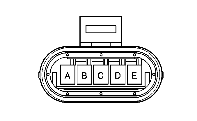
A | GRY | 435 | EGR Solenoid Control | ||||
B | BLK | 2753 | EGR Pintle Position Sensor Ground | ||||
C | BRN | 1456 | EGR Valve Position Signal | ||||
D | GRY/BLK | 2702 | 5 Volt Reference | ||||
E | RED | 1676 | EGR Valve Supply Voltage | ||||
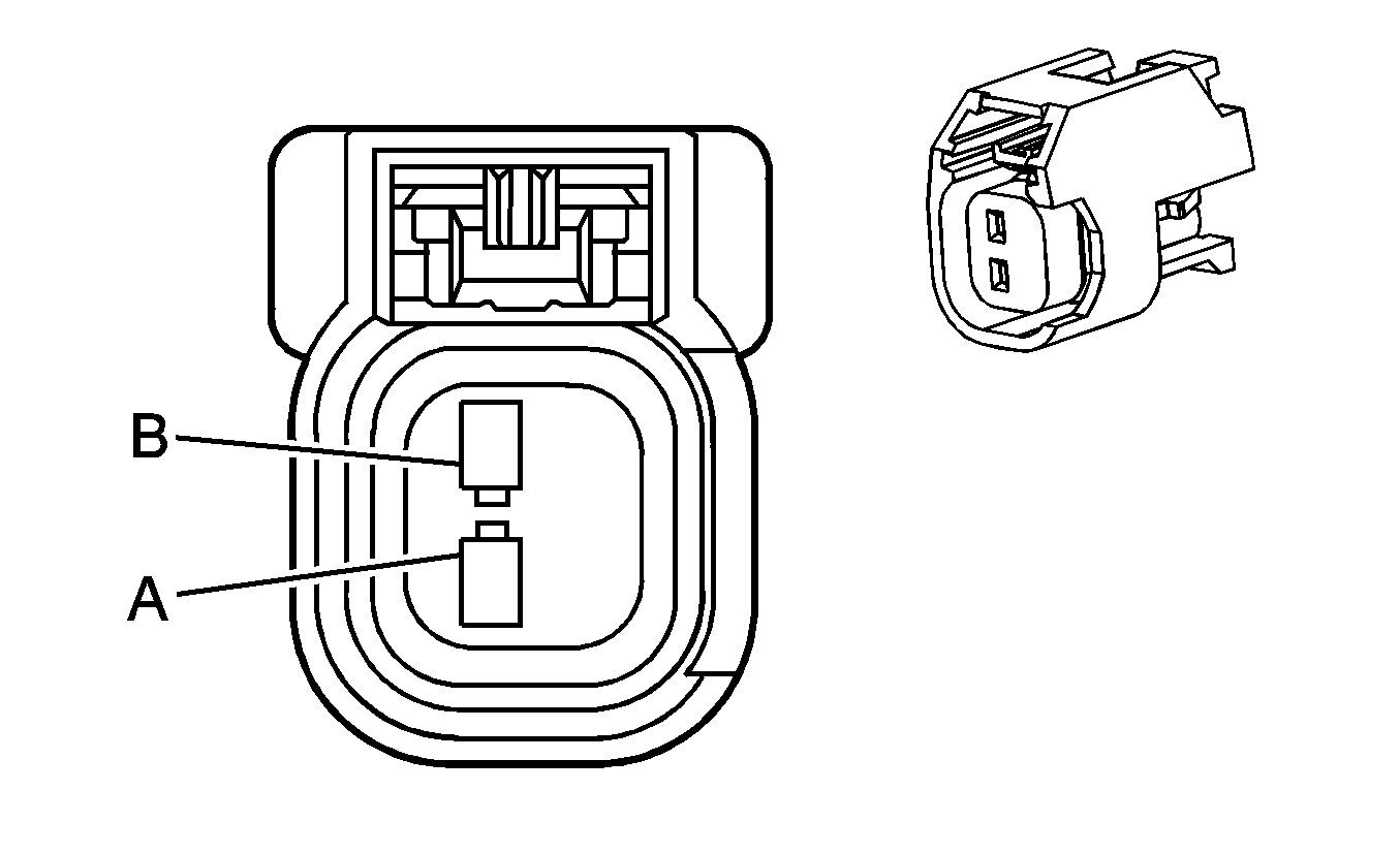
| |||||||
|---|---|---|---|---|---|---|---|
Connector Part Information |
| ||||||
Pin | Wire Color | Circuit No. | Function | ||||
A | PNK/BLK | 239 | Ignition 1 Voltage - Injector 1 | ||||
A | PNK/WHT | 239 | Ignition 1 Voltage - Injector 4 | ||||
A | PNK | 239 | Ignition 1 Voltage - Injectors 6 and 7 | ||||
A | PNK | 339 | Ignition 1 Voltage Injectors 2, 3, and 8 | ||||
A | PNK/BLK | 339 | Ignition 1 Voltage - Injector 5 | ||||
B | BLK | 1744 | Fuel Injector 1 Control | ||||
B | LT GRN/BLK | 1745 | Fuel Injector 2 Control | ||||
B | PNK/BLK | 1746 | Fuel Injector 3 Control | ||||
B | LT BLU/BLK | 844 | Fuel Injector 4 Control | ||||
B | BLK/WHT | 845 | Fuel Injector 5 Control | ||||
B | YEL BLK | 846 | Fuel Injector 6 Control | ||||
B | RED/BLK | 877 | Fuel Injector 7 Control | ||||
B | DK BLU/WHT | 878 | Fuel Injector 8 Control | ||||
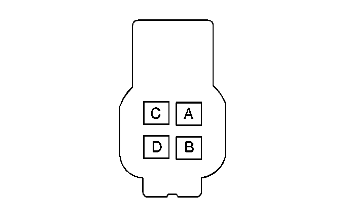
| |||||||
|---|---|---|---|---|---|---|---|
Connector Part Information |
| ||||||
Pin | Wire Color | Circuit No. | Function | ||||
A | PPL | 1589 | Fuel Level Sensor Signal | ||||
B | GRY | 120 | Fuel Pump Supply Voltage | ||||
C | BLK | 1050 | Ground | ||||
D | BLK/WHT | 552 | Low Reference | ||||
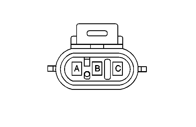
| |||||||
|---|---|---|---|---|---|---|---|
Connector Part Information |
| ||||||
Pin | Wire Color | Circuit No. | Function | ||||
A | BLK | 2759 | Low Reference | ||||
B | DK GRN | 890 | Fuel Tank Pressure Sensor Signal | ||||
C | GRY | 2709 | 5 Volt Reference | ||||
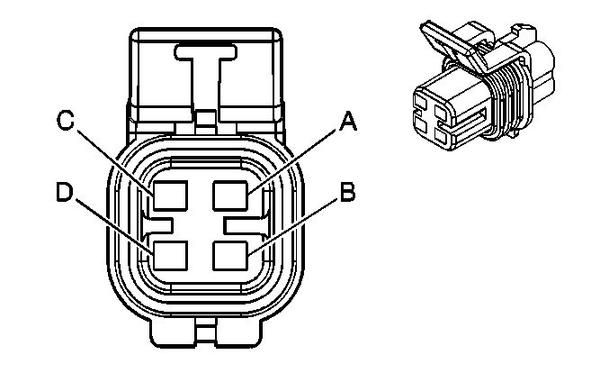
| |||||||
|---|---|---|---|---|---|---|---|
Connector Part Information |
| ||||||
Pin | Wire Color | Circuit No. | Function | ||||
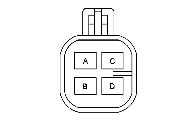
A | TAN/WHT | 1669 | HO2S Low Signal Bank 1 Sensor 1 | ||||
B | PPL/WHT | 1668 | HO2S High Signal Bank 1 Sensor 1 | ||||
C | BLK | 3122 | HO2S Heater Control Low | ||||
D | PNK/BLK | 539 | Ignition 1 Voltage | ||||
| |||||||
|---|---|---|---|---|---|---|---|
Connector Part Information |
| ||||||
Pin | Wire Color | Circuit No. | Function | ||||
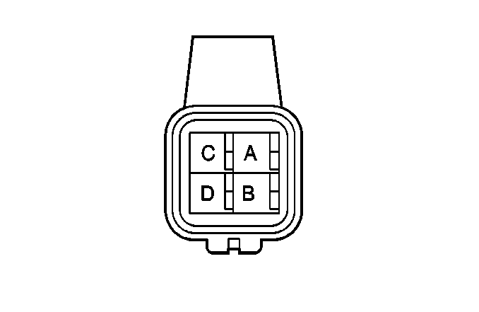
A | TAN/WHT | 1677 | HO2S Low Signal Bank 1 Sensor 2 | ||||
B | PPL/WHT | 1678 | HO2S High Signal Bank 1 Sensor 2 | ||||
C | BLK | 1423 | HO2S Heater Control Low | ||||
D | PNK | 539 | Ignition 1 Voltage | ||||
| |||||||
|---|---|---|---|---|---|---|---|
Connector Part Information |
| ||||||
Pin | Wire Color | Circuit No. | Function | ||||
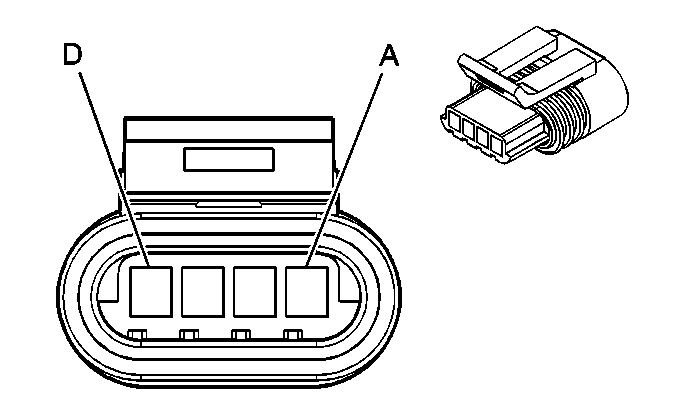
A | TAN | 1664 | HO2S Low Signal Bank 2 Sensor 1 | ||||
B | PPL/WHT | 1665 | HO2S High Signal Bank 2 Sensor 1 | ||||
C | BLK/WHT | 3112 | HO2S Heater Low Control | ||||
D | DK GRN | 676 | Ignition 1 Voltage | ||||
| |||||||
|---|---|---|---|---|---|---|---|
Connector Part Information |
| ||||||
Pin | Wire Color | Circuit No. | Function | ||||
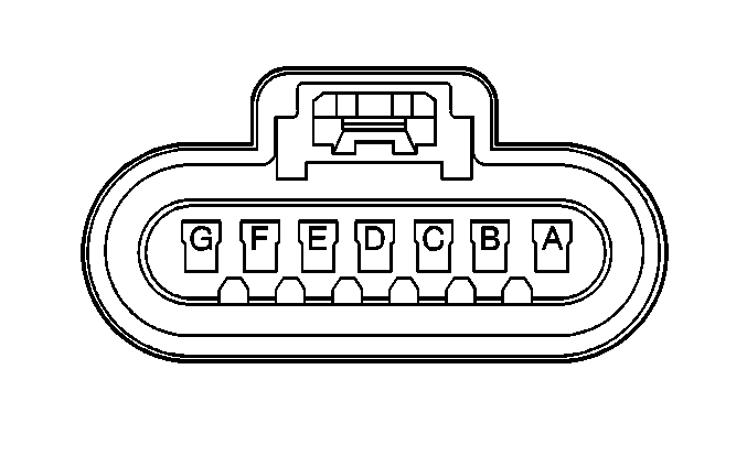
A | LT GRN/BLK | 444 | IAC Coil B Low | ||||
B | LT GRN/WHT | 1749 | IAC Coil B High | ||||
C | LT BLU/BLK | 1748 | IAC Coil A Low | ||||
D | LT BLU/WHT | 1747 | IAC Coil A High | ||||
| |||||||
|---|---|---|---|---|---|---|---|
Connector Part Information |
| ||||||
Pin | Wire Color | Circuit No. | Function | ||||
A | PNK/WHT | 839 | Ignition 1 Voltage | ||||
B | BLK/WHT | 1551 | Ground | ||||
C | YEL | 2174 | Electronic Spark Timing Return | ||||
D | DK GRN/WHT | 2124 | IC 4 Control | ||||
E | LT BLU/WHT | 2126 | IC 6 Control | ||||
F | PPL/WHT | 2128 | IC 8 Control | ||||
G | RED/WHT | 2122 | IC 2 Control | ||||

| |||||||
|---|---|---|---|---|---|---|---|
Connector Part Information |
| ||||||
Pin | Wire Color | Circuit No. | Function | ||||
A | PNK | 839 | Ignition 1 Voltage | ||||
B | BLK/WHT | 1551 | Ground | ||||
C | GRY/BLK | 2175 | Electronic Spark Timing Return | ||||
D | DK GRN | 2125 | IC 5 Control | ||||
E | LT BLU | 2123 | IC 3 Control | ||||
F | PPL | 2121 | IC 1 Control | ||||
G | RED | 2127 | IC 7 Control | ||||
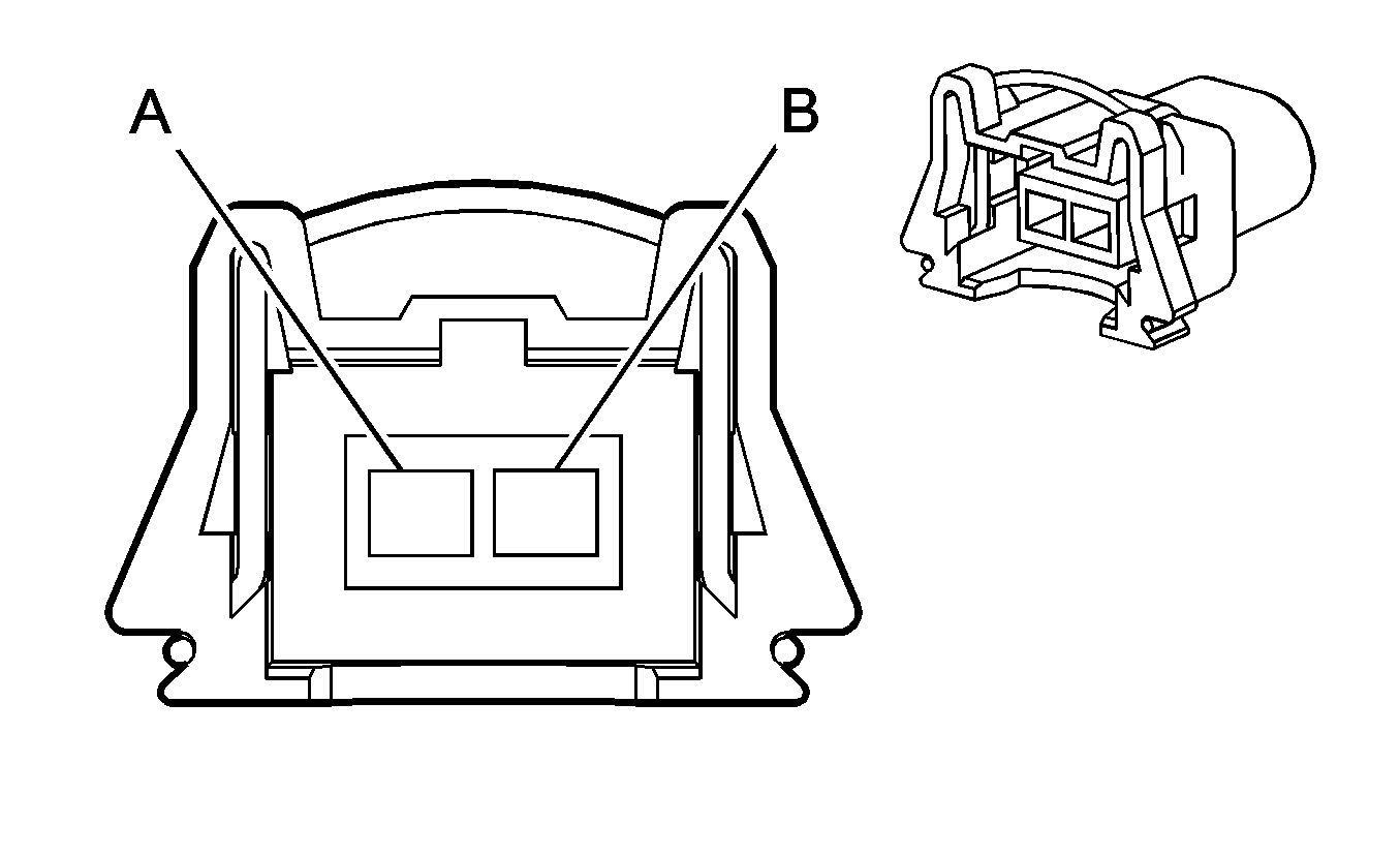
| |||||||
|---|---|---|---|---|---|---|---|
Connector Part Information |
| ||||||
Pin | Wire Color | Circuit No. | Function | ||||
A | DK BLU | 496 | KS (1) Signal | ||||
B | GRY | 1716 | Knock Sensor Return | ||||
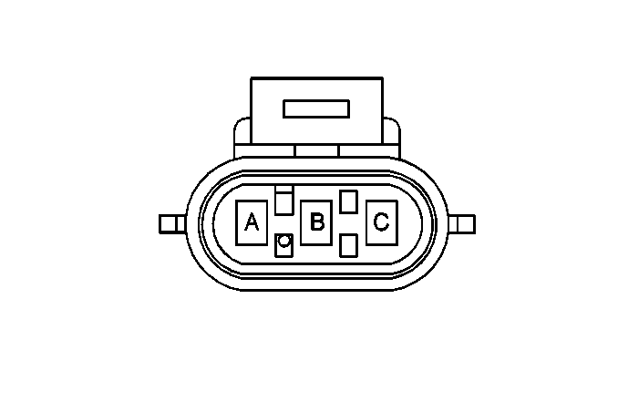
| |||||||
|---|---|---|---|---|---|---|---|
Connector Part Information |
| ||||||
Pin | Wire Color | Circuit No. | Function | ||||
A | ORN/BLK | 469 | Low Reference | ||||
B | LT GRN | 432 | MAP Sensor Signal | ||||
C | GRY | 2704 | 5 Volt Reference | ||||
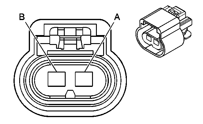
| |||||||
|---|---|---|---|---|---|---|---|
Connector Part Information |
| ||||||
Pin | Wire Color | Circuit No. | Function | ||||
A | BLK | 2760 | Low Reference | ||||
B | TAN | 472 | IAT Sensor Signal | ||||
C | BLK/WHT | 1151 | Ground | ||||
D | PNK/WHT | 139 | Ignition 1 Voltage | ||||
E | YEL | 492 | MAF Sensor Signal | ||||
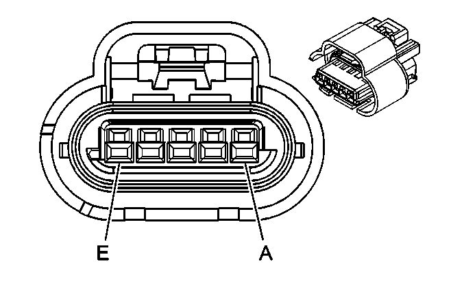
| |||||||
|---|---|---|---|---|---|---|---|
Connector Part Information |
| ||||||
Pin | Wire Color | Circuit No. | Function | ||||
A | BLK | 1250 | Ground | ||||
B | DK BLU | 78 | AIR Pump Supply Voltage | ||||
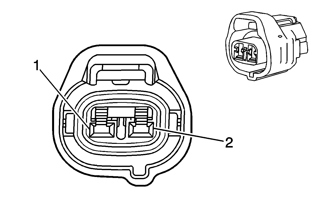
| |||||||
|---|---|---|---|---|---|---|---|
Connector Part Information |
| ||||||
Pin | Wire Color | Circuit No. | Function | ||||
1 | PNK | 139 | Ignition 1 Voltage | ||||
2 | PNK/BLK | 429 | Air Solenoid Control | ||||
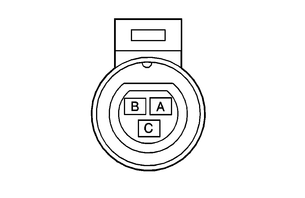
| |||||||
|---|---|---|---|---|---|---|---|
Connector Part Information |
| ||||||
Pin | Wire Color | Circuit No. | Function | ||||
A | GRY | 2701 | 5 Volt Reference | ||||
B | BLK/WHT | 2752 | Low Reference | ||||
C | DK BLU | 417 | TP Sensor Signal | ||||

| |||||||
|---|---|---|---|---|---|---|---|
Connector Part Information |
| ||||||
Pin | Wire Color | Circuit No. | Function | ||||
A | PPL | 401 | Signal Low-Front | ||||
B | YEL | 400 | Signal High-Front | ||||
