Tools Required
J 28733-B Front Hub Spindle Remover
Removal Procedure
- Raise and Support the vehicle. Refer to Lifting and Jacking the Vehicle in General Information.
- Remove the tire and wheel. Refer to Tire and Wheel Removal and Installation in Tires and Wheels.
- Clean the drive axle threads of all dirt. Lubricate the threads.
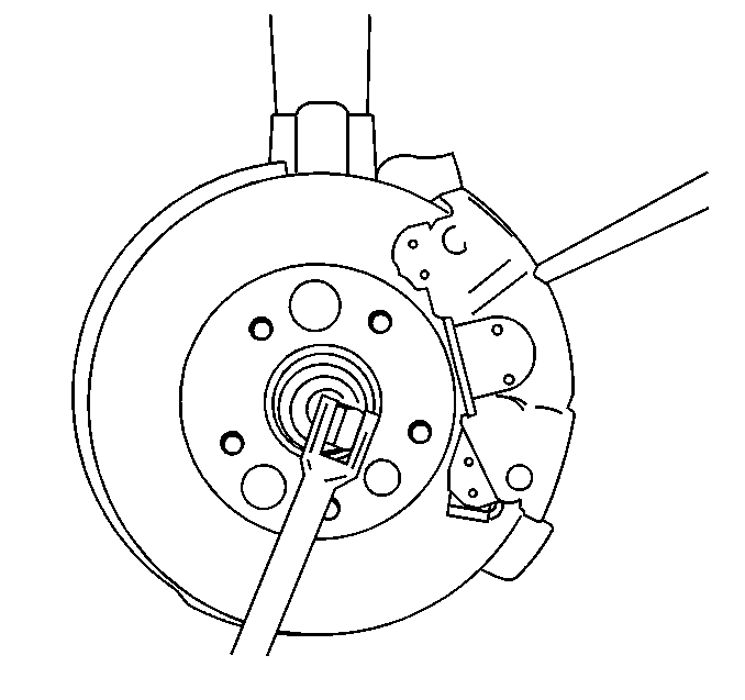
- Insert a drift punch or a screwdriver into the caliper and the rotor in order to prevent the rotor from turning.
- Remove the drive axle nut.
- Remove the brake rotor. Refer to Brake Rotor Replacement in Disc Brakes.
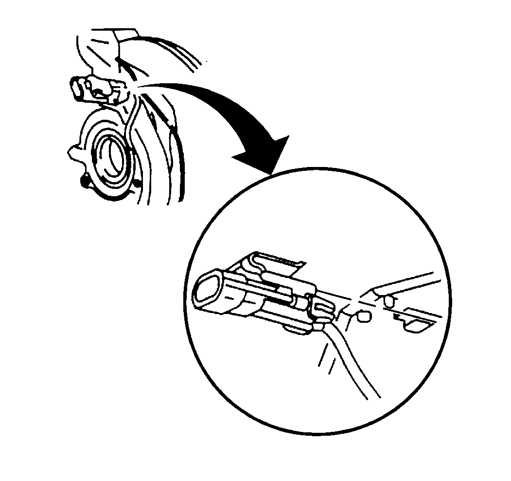
- Disconnect the ABS front wheel speed sensor connector. Unclip the connector from the dust shield.
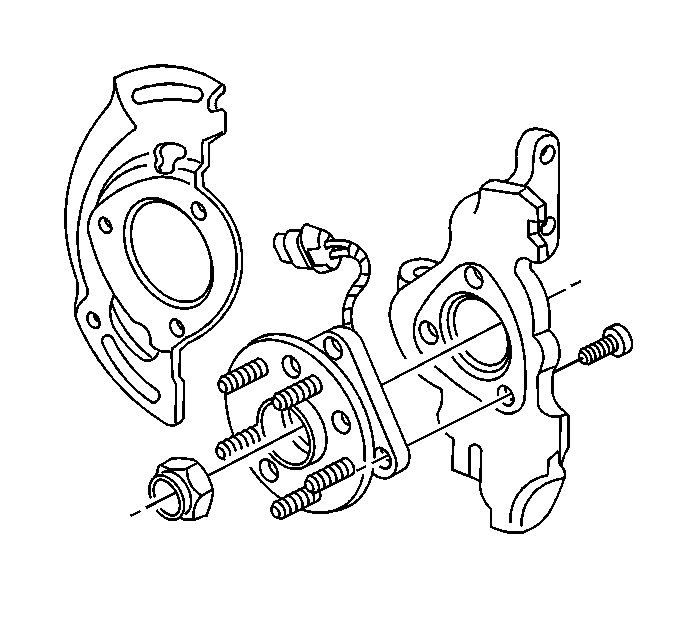
- Remove the wheel bearing and hub retaining bolts.
- Use the J 28733-B in order to separate the hub and bearing from the drive axle.
- Clean the rust and the foreign material from the following components in order to allow proper seating of the bearing into the knuckle:


Important: Replace the hub and bearing only as an assembly.
| • | The knuckle mounting face |
| • | The bore |
| • | The chamber |
Installation Procedure
- Remove the protective plastic cover before installation. Do not handle the knuckle or hub assembly by the ABS sensor wire.
- Carefully install the dust shield. Do not damage the bearing outboard lip seal, or the wheel bearing and hub retaining bolts.
- Apply a thin layer of grease to the steering knuckle bore.
- Install the wheel bearing and hub and dust shield to the steering knuckle.
- Install the wheel bearing and hub retaining bolts.
- Install the new drive axle nut, draw hub and bearing onto the axle.
- Connect the ABS front wheel speed sensor connector. Clip the connector to its proper location.
- Install the brake rotor. Refer to Brake Rotor Replacement in Disc Brakes.
- Insert a drift punch or a screwdriver into the caliper and rotor in order to prevent the rotor from turning.
- Install the tire and wheel. Refer to Tire and Wheel Removal and Installation in Tires and Wheels.
- Lower the vehicle.

Notice: Use the correct fastener in the correct location. Replacement fasteners must be the correct part number for that application. Fasteners requiring replacement or fasteners requiring the use of thread locking compound or sealant are identified in the service procedure. Do not use paints, lubricants, or corrosion inhibitors on fasteners or fastener joint surfaces unless specified. These coatings affect fastener torque and joint clamping force and may damage the fastener. Use the correct tightening sequence and specifications when installing fasteners in order to avoid damage to parts and systems.
Tighten
Tighten the wheel bearing and hub retaining bolts to 95 N·m
(70 lb ft).


Tighten
Tighten the drive axle nut to 160 N·m (118 lb ft).
