Notice: The assembly of some components will require the use of an assembly
lube. Always use J 36850 Transjel™ or petroleum jelly during
assembly. Greases other than the recommended assembly lube will change the
transmission fluid characteristics and cause undesirable shift
conditions and/or filter clogging.
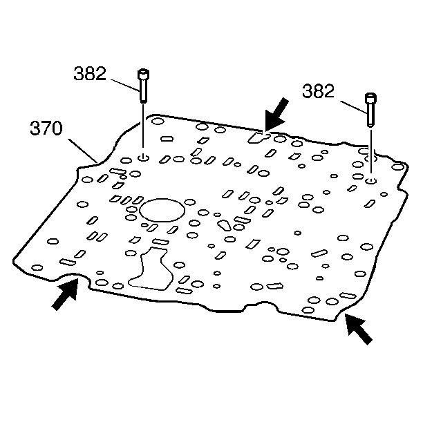
- Inspect the control valve body spacer plate (370) for the following conditions:
| • | Damaged gasket sealing surfaces |
| • | Plugged or damaged screen/seal assemblies (382) |
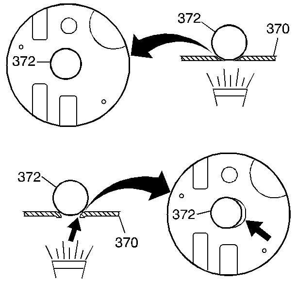
- Inspect each ball check valve seat one at a time on the spacer plate (370) for excessive peening.
| • | Place a ball check valve (372) on each seat |
| • | Use a flashlight to look for visible light between the ball check valve and the seat. |
| • | If light is visible between the ball check valve and the seat, replace the spacer plate assembly (370). |
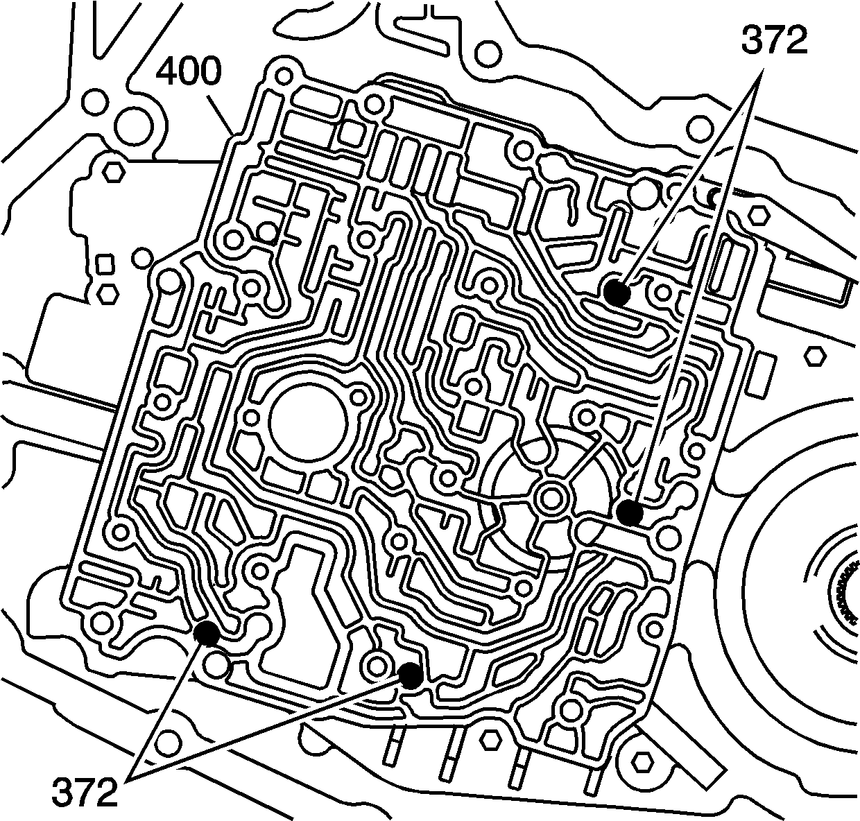
- Install four ball check valves (372) into the case cover (400), in the positions shown. Use
J 36850
.
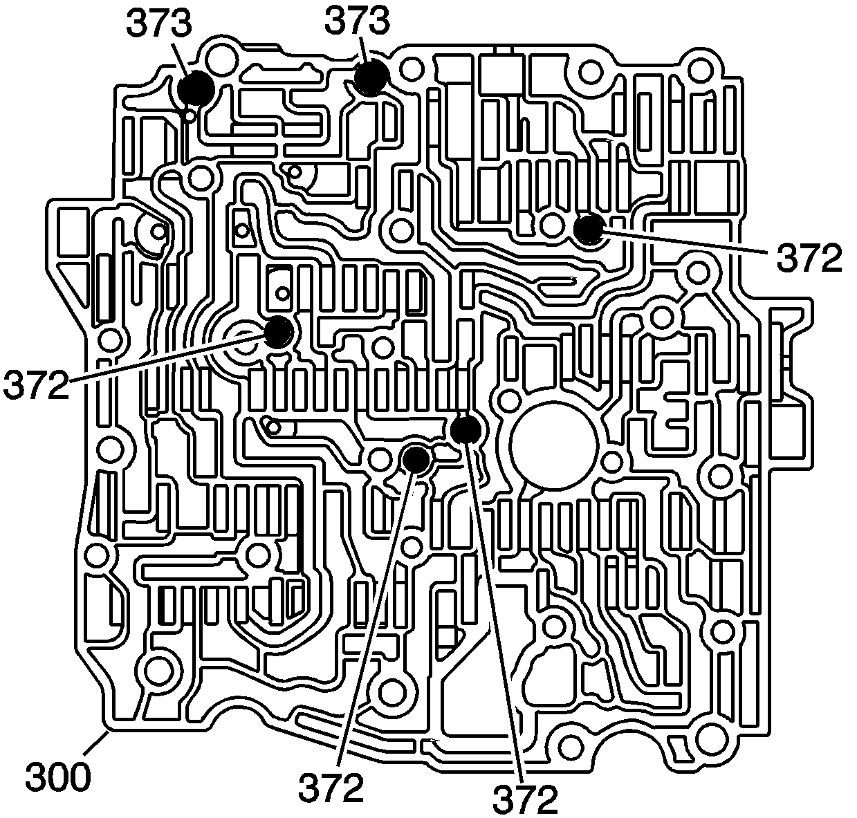
- Install the two larger ball check valves (373) and the four smaller ball check valves (372) into the control
valve body (300). Use
J 36850
.
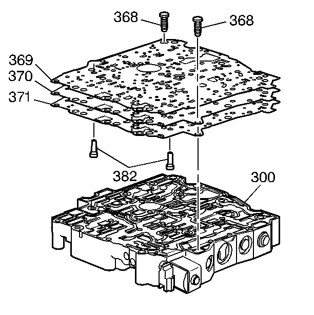
- Install the screen/seal assemblies (382) into the spacer plate assembly (370).
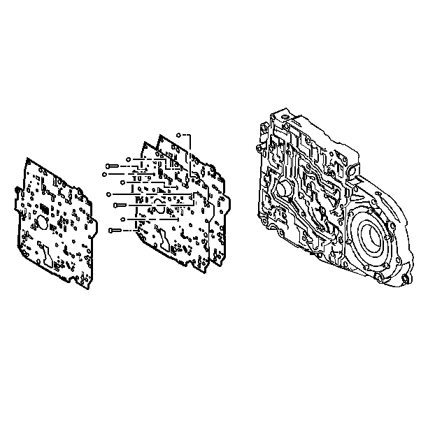
- Install the control valve body to spacer plate gasket (371), the spacer plate assembly (370) and the case cover to spacer plate gasket (369) onto the control valve body (300).
- Install the bolts (368) to hold the spacer plate and gaskets onto the control valve body (300).
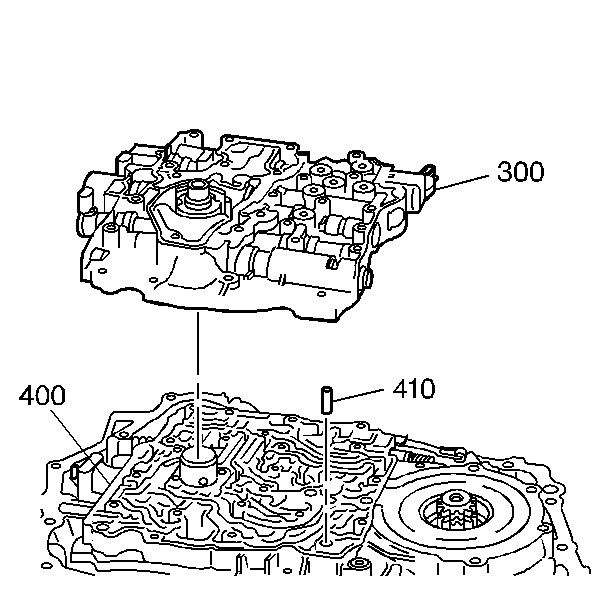
- Install the control valve body alignment sleeve (410) into the case cover (400).
Important:
| • | Use the control valve body alignment sleeve (410) and turbine shaft sleeve in the case cover (400) as guides. |
| • | Be sure that the ball check valves do not drop out of the control valve body (300) during assembly. |
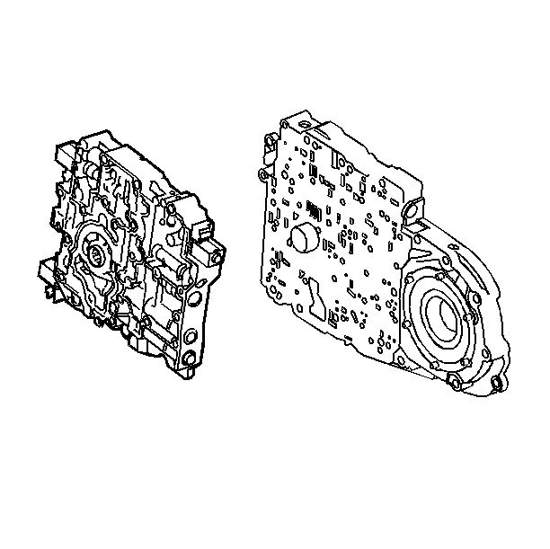
- Install the control valve body (300) onto the case cover (400).
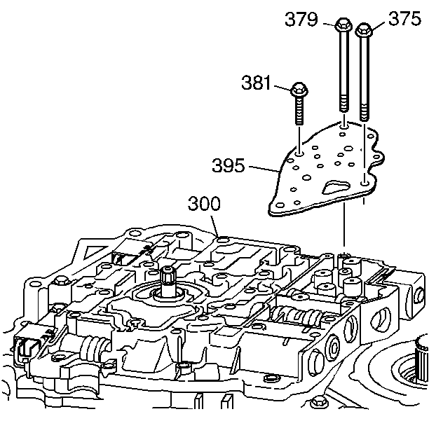
- Install the transmission fluid pressure (TFP) manual valve position switch assembly (395) onto the control valve
body (300).
Important: Finger start the bolts to prevent cross-threading.
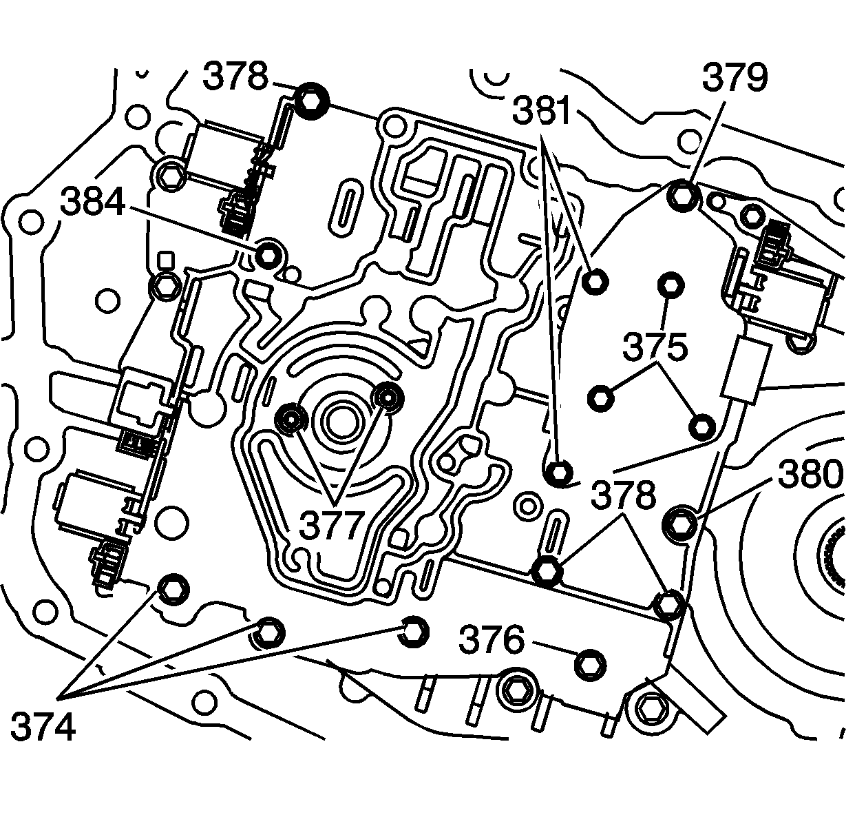
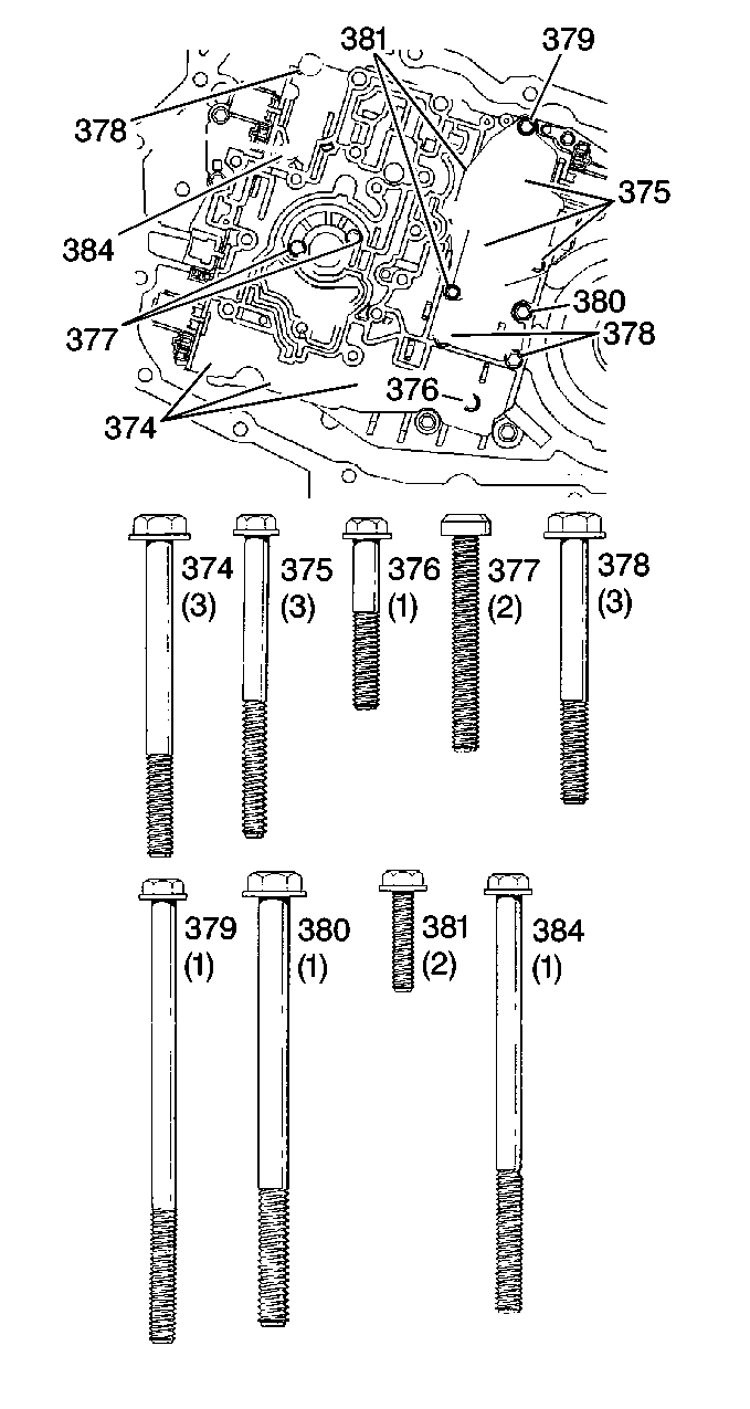
- Install the control valve body bolts (374-381, 384) as indicated.
Notice: Refer to Fastener Notice in the Preface section.
Important:
| • | Tighten the bolts in a spiral pattern starting with the bolts at the center of the control valve body. |
| • | If the bolts are tightened at random, valve bores may become distorted and inhibit proper valve operation. |
- Tighten the control valve body bolts (374-381, 384) as indicated by the following list.
Tighten
| • | The 374 to 12 N·m (106 lb in) |
| • | The 375 to 12 N·m (106 lb in) |
| • | The 376 to 12 N·m (106 lb in) |
| • | The 377 to 12 N·m (106 lb in) |
| • | The 378 to 12 N·m (106 lb in) |
| • | The 379 to 16 N·m (11 lb ft) |
| • | The 380 to 25 N·m (18 lb ft) |
| • | The 381 to 8 N·m (70 lb in) |
| • | The 384 to 12 N·m (106 lb in) |
- Install the oil pump. Refer to
Oil Pump Replacement
.
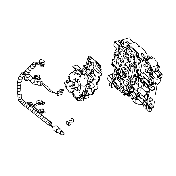
- Install the wiring harness.
- Install the case side cover. Refer to
Control Valve Body Cover Replacement
.
- Fill the transaxle to the proper level. Refer to
Fluid Capacity Specifications
.
- Inspect the transaxle fluid level. Refer to
Transmission Fluid Check
.
- Inspect for fluid leaks.
Important: It is recommended that transmission adaptive pressure (TAP) information be reset.
Resetting the TAP values using a scan tool will erase all learned values in all cells. As a result, The ECM, PCM or TCM will
need to relearn TAP values. Transmission performance may be affected as new TAP values are learned.
- Reset the TAP values. Refer to
Adapt Function
.

