| Table 1: | Audio Amplifier C1 (U80) |
| Table 2: | Audio Amplifier C2 (U80) |
| Table 3: | Radio |
| Table 4: | Radio (w/U80) |
| Table 5: | Radio Antenna Module |
| Table 6: | Remote Playback Device -- CD Changer |
| Table 7: | Speaker -- LF Door |
| Table 8: | Speaker -- LF Door Tweeter |
| Table 9: | Speaker -- LR |
| Table 10: | Speaker -- LR Door |
| Table 11: | Speaker -- LR Subwoofer (w/u80) |
| Table 12: | Speaker -- RF Door |
| Table 13: | Speaker -- RR |
| Table 14: | Speaker -- RR Door |
| Table 15: | Speaker -- RR Subwoofer (w/U80) |
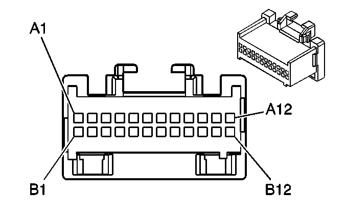
| |||||||
|---|---|---|---|---|---|---|---|
Connector Part Information |
| ||||||
Pin | Wire Color | Circuit No. | Function | ||||
A1 | PNK | 608 | 14 Volt Reference | ||||
A2-A6 | -- | -- | Not Used | ||||
A7 | DK GRN | 117 | Right Front Speaker Output (-) | ||||
A8 | LT GRN | 200 | Right Front Speaker Output (+) | ||||
A9 | DK BLU | 46 | Right Rear Speaker Output (+) | ||||
A10 | LT BLU | 115 | Right Rear Speaker Output (-) | ||||
A11 | GRY | 118 | Left Front Speaker Output (-) | ||||
A12 | TAN | 201 | Left Front Speaker Output (+) | ||||
B1-B4 | -- | -- | Not Used | ||||
B5 | TAN | 511 | Left Front Low Level Audio Signal (+) | ||||
B6 | LT GRN/BLK | 512 | Right Front Low Level Audio Signal (+) | ||||
B7 | BRN/WHT | 599 | Left Rear Low Level Audio Signal (+) | ||||
B8 | DK BLU | 546 | Right Rear Low Level Audio Signal (+) | ||||
B9 | LT GRN | 1948 | Right Front Low Level Audio Signal (-) | ||||
B10 | BLK | 1946 | Right Rear Low Level Audio Signal (-) | ||||
B11 | BRN | 1999 | Left Rear Low Level Audio Signal (-) | ||||
B12 | DK GRN | 1947 | Left Front Low Level Audio Signal (-) | ||||
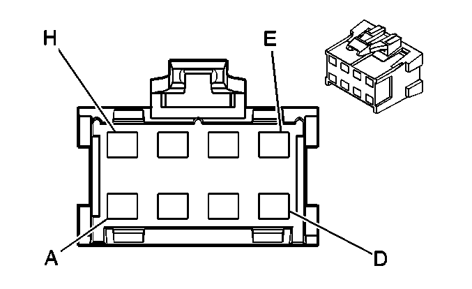
| |||||||
|---|---|---|---|---|---|---|---|
Connector Part Information |
| ||||||
Pin | Wire Color | Circuit No. | Function | ||||
A | BLK/WHT | 551 | Ground | ||||
B | YEL | 116 | Left Rear Speaker Output (-) | ||||
C | DK BLU/WHT | 346 | Left Subwoofer Speaker Output (+) | ||||
D | DK GRN | 1795 | Right Subwoofer Output (+) | ||||
E | LT BLU/BLK | 315 | Right Subwoofer Output (-) | ||||
F | LT GRN/BLK | 1794 | Left Subwoofer Output (-) | ||||
G | BRN | 199 | Left Rear Speaker Output (+) | ||||
H | RED | 1242 | Battery Positive Voltage | ||||
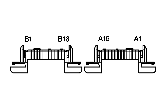
| |||||||
|---|---|---|---|---|---|---|---|
Connector Part Information |
| ||||||
Pin* | Wire Color | Circuit No. | Function | ||||
A1 | FW | 1807 | Class 2 Serial Data (Primary) | ||||
A2 | FW | 1807 | Class 2 Serial Data (Primary) | ||||
A3 | FW | 608 | 14 Volt Reference | ||||
A4 | FW | 1486 | FM Composite Signal | ||||
A5-A6 | -- | -- | Not Used | ||||
A7 | FW | 659 | Cellular Telephone Voice Low Reference | ||||
A8 | FW | 658 | Cellular Telephone Voice Signal | ||||
A9 | FW | 372 | Remote Radio Audio Output (-) | ||||
A10 | FW | 367 | Remote Radio Audio Output (-) | ||||
A11 | FW | 368 | Remote Radio Right Audio Signal | ||||
A12 | FW | 199 | Left Rear Speaker Output (+) | ||||
A13 | FW | 116 | Left Rear Speaker Output (-) | ||||
A14 | FW | 117 | Right Front Speaker Output (-) | ||||
A15 | FW | 200 | Right Front Speaker Output (+) | ||||
A16 | FW | 551 | Ground | ||||
B1 | FW | 2240 | Battery Positive Voltage | ||||
B2 | FW | 2240 | Battery Positive Voltage | ||||
B3 | FW | 1487 | Antenna Enable Signal | ||||
B4 | FW | 1491 | Backlight Lamps Control | ||||
B5 | FW | 450 | Ground | ||||
B6-B10 | -- | -- | Not Used | ||||
B11 | FW | 514 | Ground | ||||
B12 | FW | 201 | Left Front Speaker Output (+) | ||||
B13 | FW | 118 | Left Front Speaker Output (-) | ||||
B14 | FW | 115 | Right Rear Speaker Output (-) | ||||
B15 | FW | 46 | Right Rear Speaker Output (+) | ||||
B16 | FW | 551 | Ground | ||||
* A Pins = Top B Pins = Bottom | |||||||

| |||||||
|---|---|---|---|---|---|---|---|
Connector Part Information |
| ||||||
Pin* | Wire Color | Circuit No. | Function | ||||
A1 | FW | 1807 | Class 2 Serial Data (Primary) | ||||
A2 | FW | 1807 | Class 2 Serial Data (Primary) | ||||
A3 | FW | 608 | 14 Volt Reference | ||||
A4 | FW | 1486 | FM Composite Signal | ||||
A5-A6 | -- | -- | Not Used | ||||
A7 | FW | 659 | Cellular Telephone Voice Low Reference | ||||
A8 | FW | 658 | Cellular Telephone Voice Signal | ||||
A9 | FW | 372 | Remote Radio Audio Output (-) | ||||
A10 | FW | 367 | Remote Radio Left Audio Signal | ||||
A11 | FW | 368 | Remote Radio Right Audio Signal | ||||
A12 | Flex | 599 | Left Rear Low Level Audio Signal (+) | ||||
A13 | FW | 1999 | Left Rear Low Level Audio Signal (-) | ||||
A14 | FW | 1948 | Right Front Low Level Audio Signal (-) | ||||
A15 | Flex | 512 | Right Front Low Level Audio Signal (+) | ||||
A16 | FW | 551 | Ground | ||||
B1 | FW | 2240 | Battery Positive Voltage | ||||
B2 | FW | 2240 | Battery Positive Voltage | ||||
B3 | FW | 1487 | Antenna Enable Signal | ||||
B4 | FW | 1491 | Backlight Lamps Control | ||||
B5 | FW | 450 | Ground | ||||
B6 | FW | 551 | Ground | ||||
B7-B10 | -- | -- | Not Used | ||||
B11 | FW | 514 | Ground | ||||
B12 | FW | 511 | Left Front Low Level Audio Signal (+) | ||||
B13 | FW | 1947 | Left Front Low Level Audio Signal (-) | ||||
B14 | FW | 1946 | Right Rear Low Level Audio Signal (-) | ||||
B15 | FW | 546 | Right Rear Low Level Audio Signal (+) | ||||
B16 | FW | 551 | Ground | ||||
* A Pins = Top B Pins = Bottom | |||||||
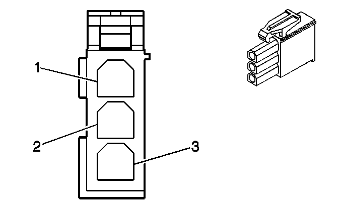
| |||||||
|---|---|---|---|---|---|---|---|
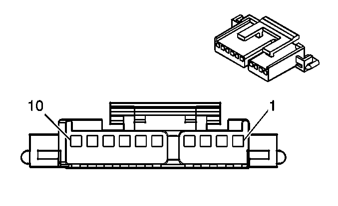
Connector Part Information |
| ||||||
Pin | Wire Color | Circuit No. | Function | ||||
1 | -- | -- | Not Used | ||||
2 | WHT | 1487 | Antenna Enable Signal | ||||
3 | WHT/ORN | 1486 | FM Composite Signal | ||||
| |||||||
|---|---|---|---|---|---|---|---|
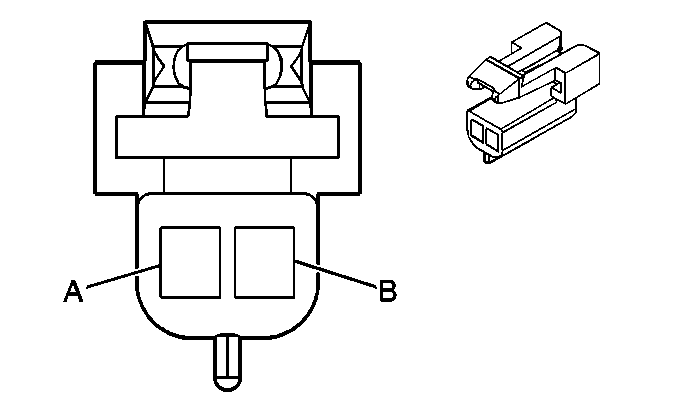
Connector Part Information |
| ||||||
Pin | Wire Color | Circuit No. | Function | ||||
1 | BRN/WHT | 367 | Remote Radio Left Audio Signal | ||||
2 | DK GRN/WHT | 368 | Remote Radio Right Audio Signal | ||||
3 | BLK/WHT | 372 | Remote Radio Audio Output (-) | ||||
4 | BARE | 1782 | Drain Wire | ||||
5 | ORN | 2640 | Battery Positive Voltage | ||||
6 | -- | -- | Not Used | ||||
7 | BLK/WHT | 551 | Ground | ||||
8 | -- | -- | Not Used | ||||
9 | PPL | 1807 | Class 2 Serial Data (Primary) | ||||
10 | PPL | 1807 | Class 2 Serial Data (Primary) | ||||
| |||||||
|---|---|---|---|---|---|---|---|
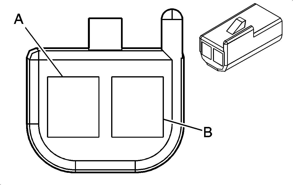
Connector Part Information |
| ||||||
Pin | Wire Color | Circuit No. | Function | ||||
A | GRY | 118 | Left Front Speaker Output (-) | ||||
B | TAN | 201 | Left Front Speaker Output (+) | ||||
| |||||||
|---|---|---|---|---|---|---|---|
Connector Part Information |
| ||||||
Pin | Wire Color | Circuit No. | Function | ||||
A | GRY | 118 | Left Front Speaker Output (-) | ||||
B | TAN | 201 | Left Front Speaker Output (+) | ||||

| |||||||
|---|---|---|---|---|---|---|---|
Connector Part Information |
| ||||||
Pin | Wire Color | Circuit No. | Function | ||||
A | YEL | 116 | Left Rear Speaker Output (+) | ||||
B | BRN | 199 | Left Rear Speaker Output (-) | ||||

| |||||||
|---|---|---|---|---|---|---|---|
Connector Part Information |
| ||||||
Pin | Wire Color | Circuit No. | Function | ||||
A | BRN | 199 | Left Rear Speaker Output (+) | ||||
B | YEL | 116 | Left Rear Speaker Output (-) | ||||

| |||||||
|---|---|---|---|---|---|---|---|
Connector Part Information |
| ||||||
Pin | Wire Color | Circuit No. | Function | ||||
A | YEL | 346 | Left Subwoofer Speaker Output (+) | ||||
B | BRN | 1794 | Left Subwoofer Speaker Output (-) | ||||

| |||||||
|---|---|---|---|---|---|---|---|
Connector Part Information |
| ||||||
Pin | Wire Color | Circuit No. | Function | ||||
A | DK GRN | 117 | Right Front Speaker Output (-) | ||||
B | LT GRN | 200 | Right Front Speaker Output (+) | ||||

| |||||||
|---|---|---|---|---|---|---|---|
Connector Part Information |
| ||||||
Pin | Wire Color | Circuit No. | Function | ||||
A | LT BLU | 115 | Right Rear Speaker Output (-) | ||||
B | DK BLU | 46 | Right Rear Speaker Output (+) | ||||

| |||||||
|---|---|---|---|---|---|---|---|
Connector Part Information |
| ||||||
Pin | Wire Color | Circuit No. | Function | ||||
A | BRN | 46 | Right Rear Speaker Output (+) | ||||
B | YEL | 115 | Right Rear Speaker Output (-) | ||||

| |||||||
|---|---|---|---|---|---|---|---|
Connector Part Information |
| ||||||
Pin | Wire Color | Circuit No. | Function | ||||
A | LT BLU | 1795 | Right Subwoofer Speaker Output (+) | ||||
B | DK BLU | 315 | Right Subwoofer Speaker Output (-) | ||||
