Refrigerant Leak Testing
Caution: Do not operate the detector in a combustible atmosphere since its sensor
operates at high temperatures or personal injury and/or damage to the equipment
may result.
Perform a refrigerant leak test on the system whenever
you suspect a leak. Also perform a refrigerant leak test after a service operation
which disturbs any of the following items:
Ensure that the vehicle has at least 0.45 kg (1 lb) of
refrigerant in the A/C refrigeration system in order to perform a leak test.
Refer to
Refrigerant Recovery and Recharging
for recharging the A/C system.
Halogen Leak Detector
Tools Required
J 39400-A Halogen
Leak Detector
Important: Halogen leak detectors are sensitive to the following items:
| • | Windshield washing solutions |
| • | Many solvents and cleaners |
| • | Some adhesives used in the vehicle |
Use this procedure in order to test the following components:
| • | The A/C compressor rear head |
Important: Follow a continuous path in order to ensure that you will not miss any
possible leaks. Test all areas of the system for leaks.
This type of leak detector is the most useful tool to locate refrigerant
leaks. The J 39400-A
is
a small unit that operates on 12 volts DC. The J 39400-A
provides an audible signal that increases
in frequency as the unit detects R-134a. Follow the instructions included
with the unit in order to properly calibrate the instrument. Use the
detector in the proper setting for the type of tested refrigerant. Set
the detector gas switch to R-134a prior to use.
The most common leaks occur at the refrigerant fittings or connections.
The leaks may be the result of any of the following conditions:
| • | Damaged O-rings or sealing washers |
| • | Lack of lubricant on O-rings |
| • | Dirt/debris across the O-ring or sealing washers |
Maintain a proper scan rate in order to successfully use the J 39400-A
or any other electronic leak detector.
Carefully follow the manufacturer's instructions regarding the following items:
In order to test for leaks, complete the following steps:
- Completely and slowly circle each joint with the probe.
- Place the tip of the probe as close as possible to the surface,
but no more than 6 mm (0.25 in) away. Do not block the probe
tip air intake.
- A leak exists when the audible tone goes from a steady 1-2 clicks
per second to a continuous alarm.
- Frequently adjust the balance knob in order to maintain the rate
of 1-2 clicks per second.

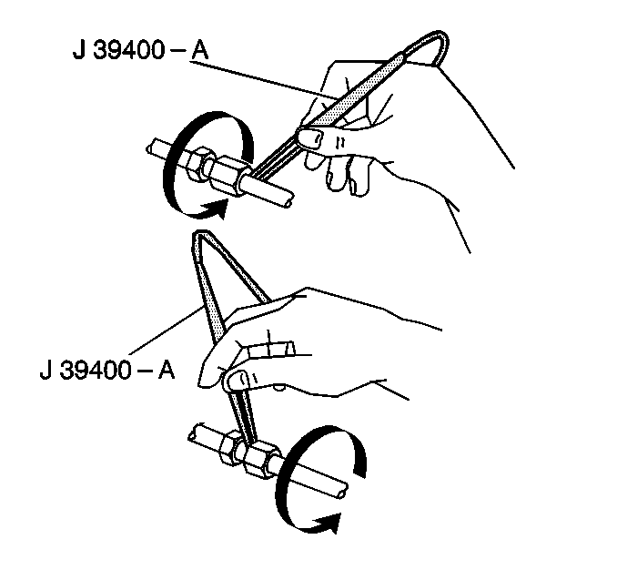
Using the J 39400-A
,
check each hose connection.

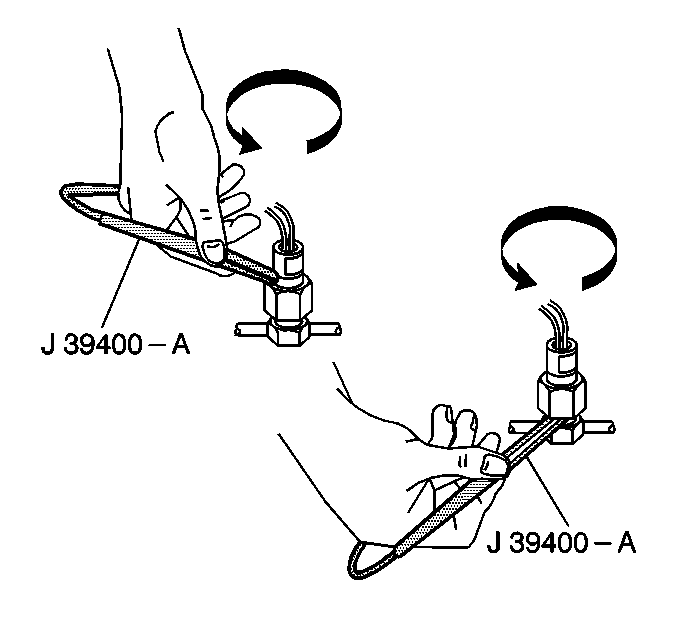
Using the J 39400-A
,
check all the electrical sensor and switches located in the lines.

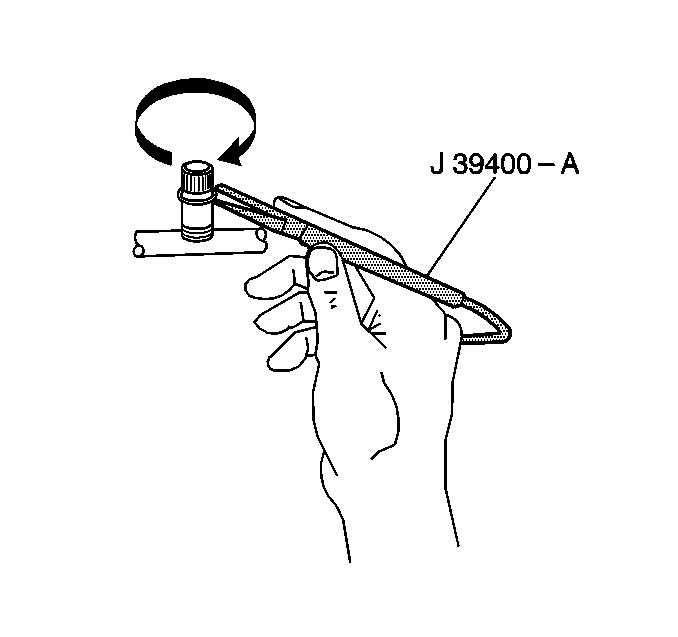
Using the J 39400-A
,
check the service ports.
Fluorescent Leak Detector
Tools Required
| • | J 41459
R-134A
A/C Tracer Dye Injector |
| • | J 42220 Universal
12V Leak Detection Lamp |
Important:
| • | J 41447 is
the only dye approved by General Motors. Not all of the R-134a dyes are
compatible with PAG oil. Some dyes decrease the oil viscosity or chemically
react with the oil. |
| • | PAG oil is water soluble. Condensation on the refrigerant lines
or the evaporator core may wash the PAG oil. Condensation may leak dye off
the line or off the core and out the condensation drain. Condensation
may make some leaks harder to find using the dye detector. Fluorescence
at the drain opening indicates a core leak. |
| • | R-134a leak detection dye requires time to work. Depending upon
the leak rate, a leak may not become visible for between 15 minutes
and 7 days. |
| • | Do not double charge the system with dye. This may cause reliability
problems. Use only the 0.25 ounce charge. |
| • | It is necessary to clean the area that a leak was detected after
a repair so that residual dye does not indicate a false diagnosis in the future.
Use a rag and the approved fluorescent dye cleaner J 43872
or equivalent to remove the excess dye. |
If you know that the system has lost charge and you cannot find a leak
with the J 39400-A
, use
a leak detection dye. This dye mixes with R-134a PAG oil. When you inspect
the leak locations with a J 42220
, the dye glows yellow/green.
The dye package contains a refrigerant leak detection notice sticker.
Complete the sticker information and place the sticker near the charge label.
Dye Injection
With the A/C system charged, use the instructions provided with the
new R-134a leak detection dye injector tool J 41459
.
To prevent a false diagnosis after dye injection, thoroughly clean any
residual dye from the access port with a rag and the approved fluorescent
dye cleaner J 43872
or
equivalent. After diagnosing a leak using dye, be sure to clean all
residual dye from the repaired area.
Service Ports/Access Valves
The primary seal for the service ports is a sealing cap. The cap contains
an O-ring or gasket that provides a leak-free seal. This cap must be installed
and tight for leak-free sealing. The following conditions will cause
a refrigerant loss:
Evaporator Core
One of the most difficult leaks to find is in the evaporator core. Complete
the following steps in order to test the core for leaks:
- Turn the blower on HI for 15 or more seconds. Turn the
blower off.
- Wait 10 minutes.
- With the blower on the lowest speed insert the leak detector probe
into one of the center instrument panel outlets. Try to get as close to the
evaporator as possible.
- A solid alarm on the detector indicates a leak.
- An evaporator core leak may be detected after a dye injection
by using the J 42220
to
inspect the drain port area.
A/C Compressor Block Fitting and Shaft Seal Leak Detection with J-39400-A
- Blow compressed air into the following locations for at least
15 seconds:
| • | Behind the A/C compressor clutch/pulley |
| • | In front of the A/C compressor clutch/pulley |
- Wait 1-2 minutes.
- Probe the area in front of the pulley.
- A solid alarm on the detector indicates a leak.
A/C Compressor Shaft Seal Leak Detection with Dye
When leak testing a A/C compressor shaft seal using the leak detection
dye method, there may be some seepage of dye from the seal, for the seal is
a dynamic seal.
- Use the instructions provided with the new R-134a leak detection
dye injector tool J 41459
and
inject dye into the vehicle's A/C system.
- Run the A/C system 15 to 30 minutes (depending on the type of
leak) to circulate the dye.
- Using the J 42220
check for a leaking A/C compressor shaft seal.
- If a leak is found, verify the leak with theJ 39400-A
because of the possible shaft seal
seepage.
- Make the necessary repair.
- Clean the area of the leak after the repair so that residual dye
does not indicate a false diagnosis in the future. Use a rag and the approved
fluorescent dye cleaner J 43872
or equivalent to remove the excess dye.


