For 1990-2009 cars only
| Figure 1: |
Ignition Switch and Controls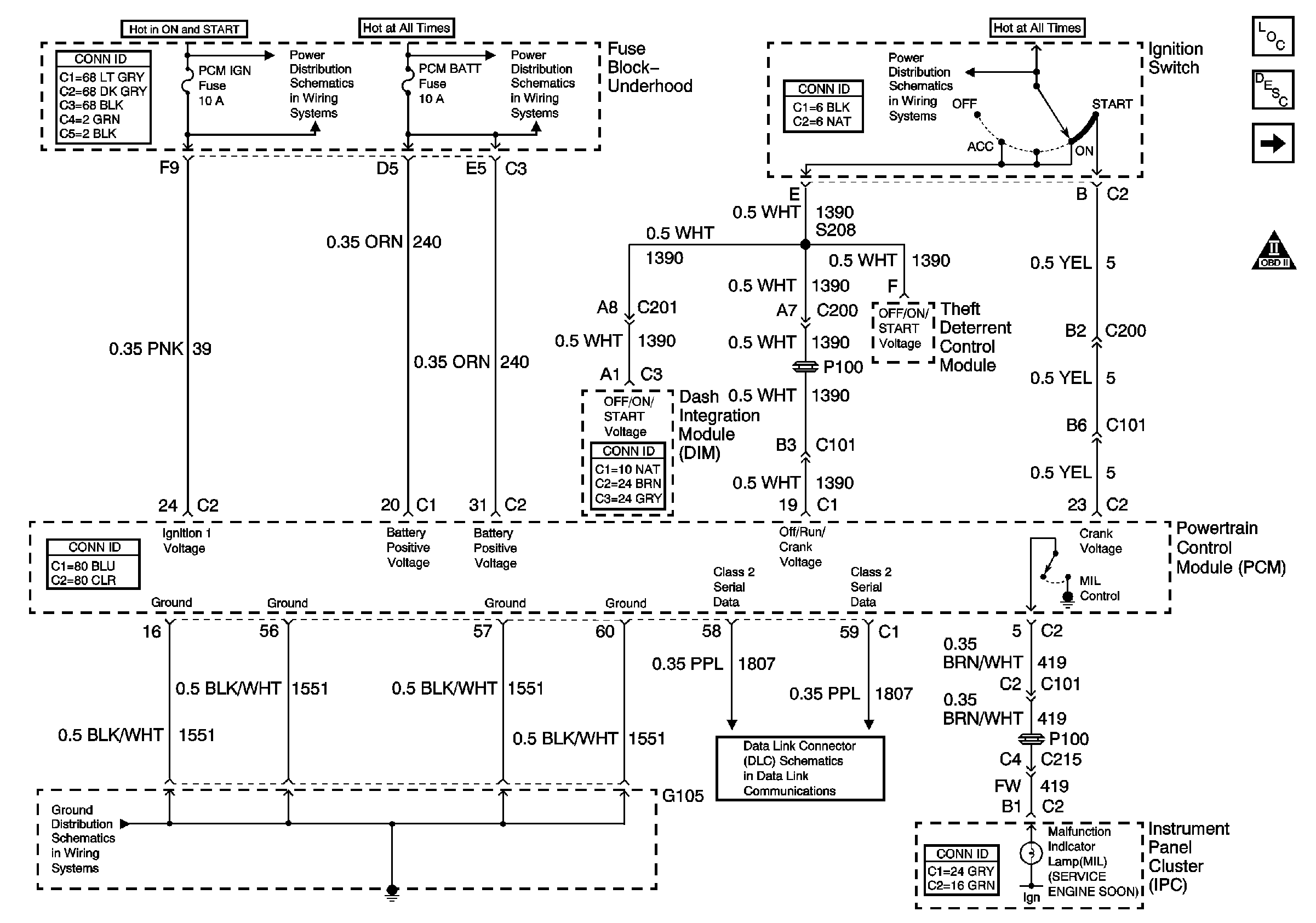
|
| Figure 2: |
Igntion Control Modules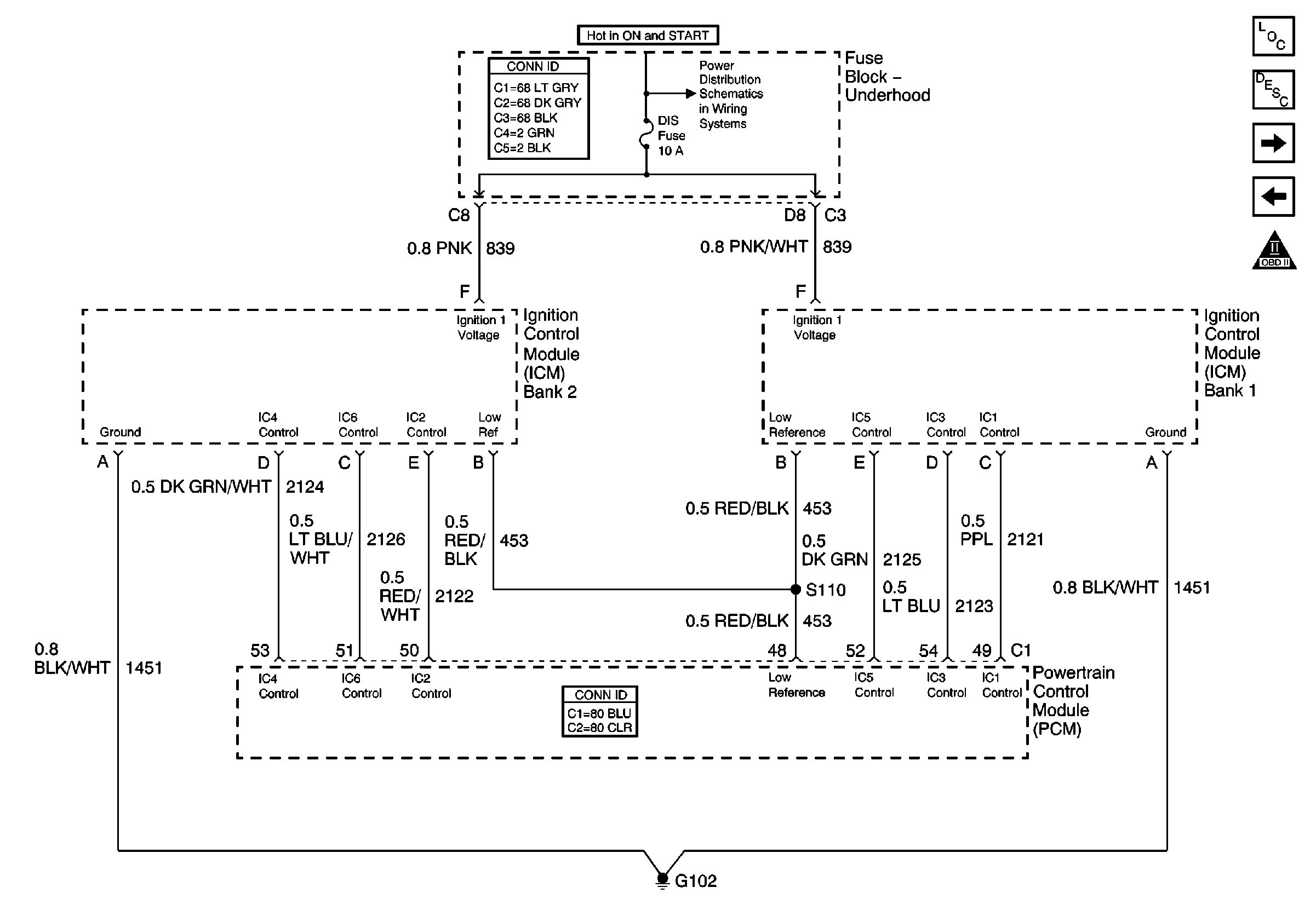
|
| Figure 3: |
Camshaft and Crankshaft Position Sensors, TCC/Cruise Release Switch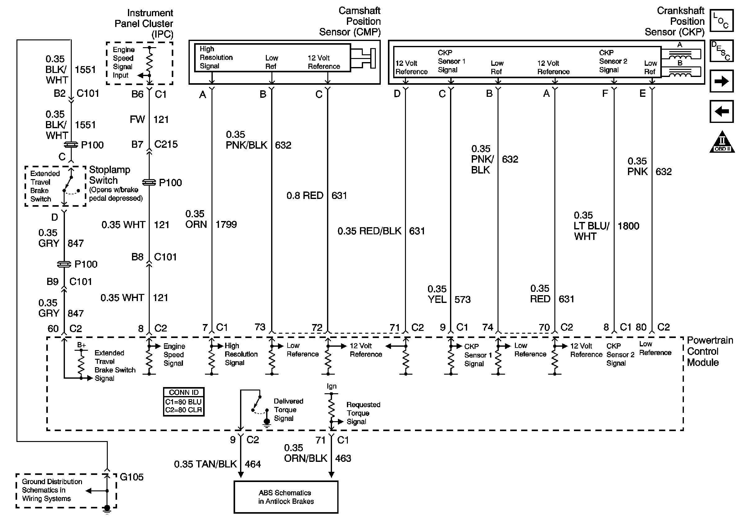
|
| Figure 4: |
Fuel Tank and Sender Assembly and Controls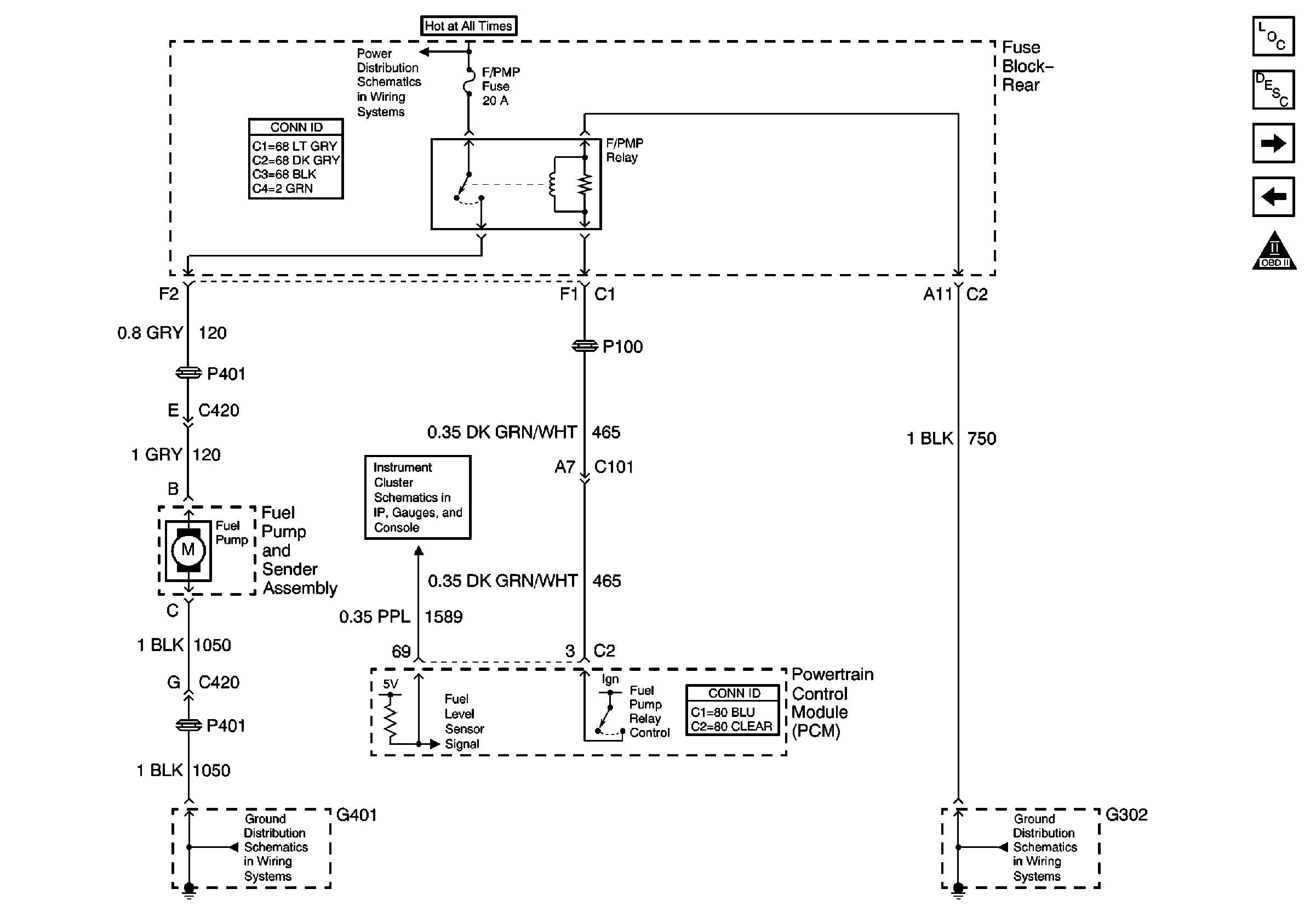
|
| Figure 5: |
Fuel Injectors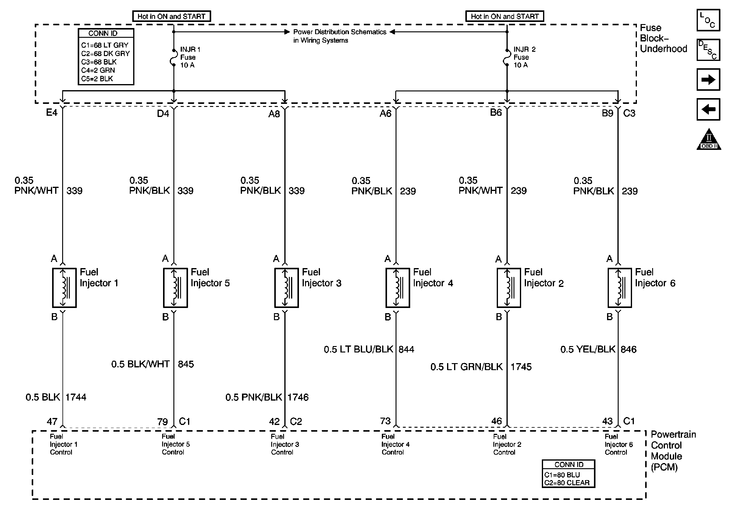
|
| Figure 6: |
Sensors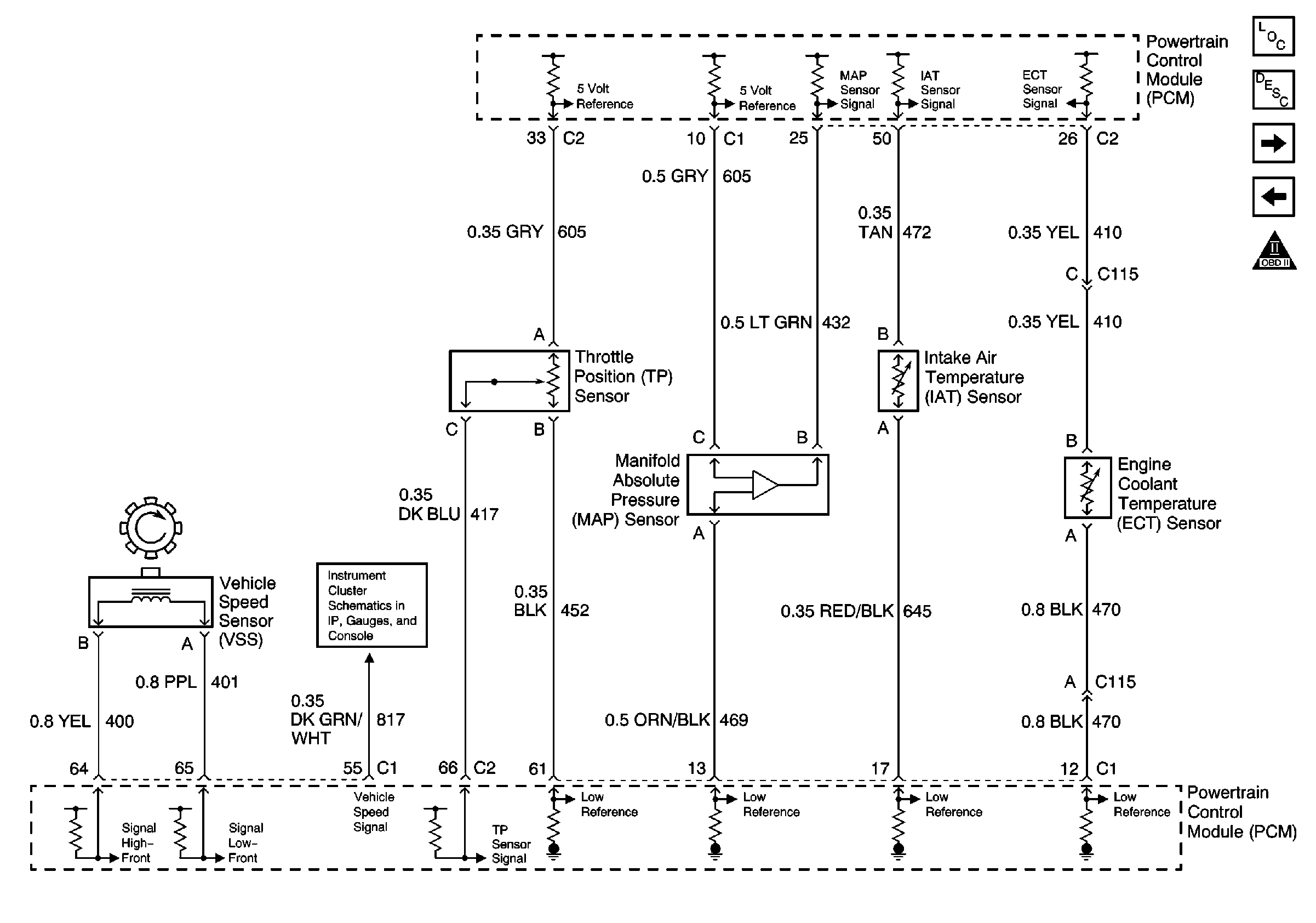
|
| Figure 7: |
Fuel Pressure Sensor and EVAP Canister Purge Vent Valve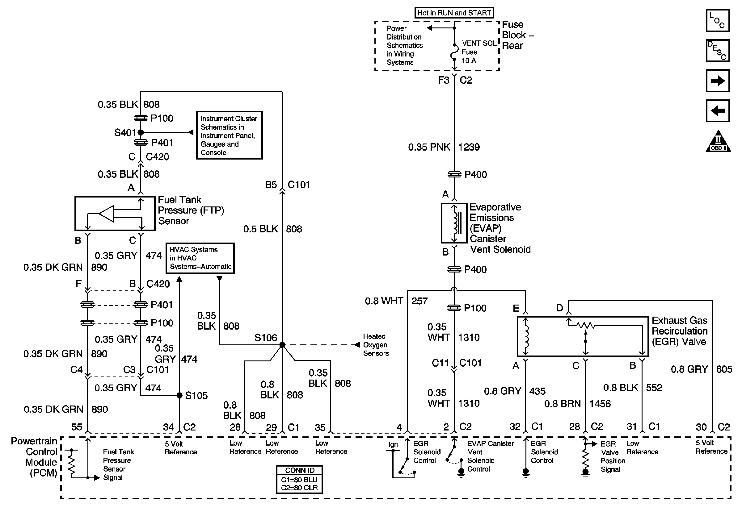
|
| Figure 8: |
Heated Oxygen Sensors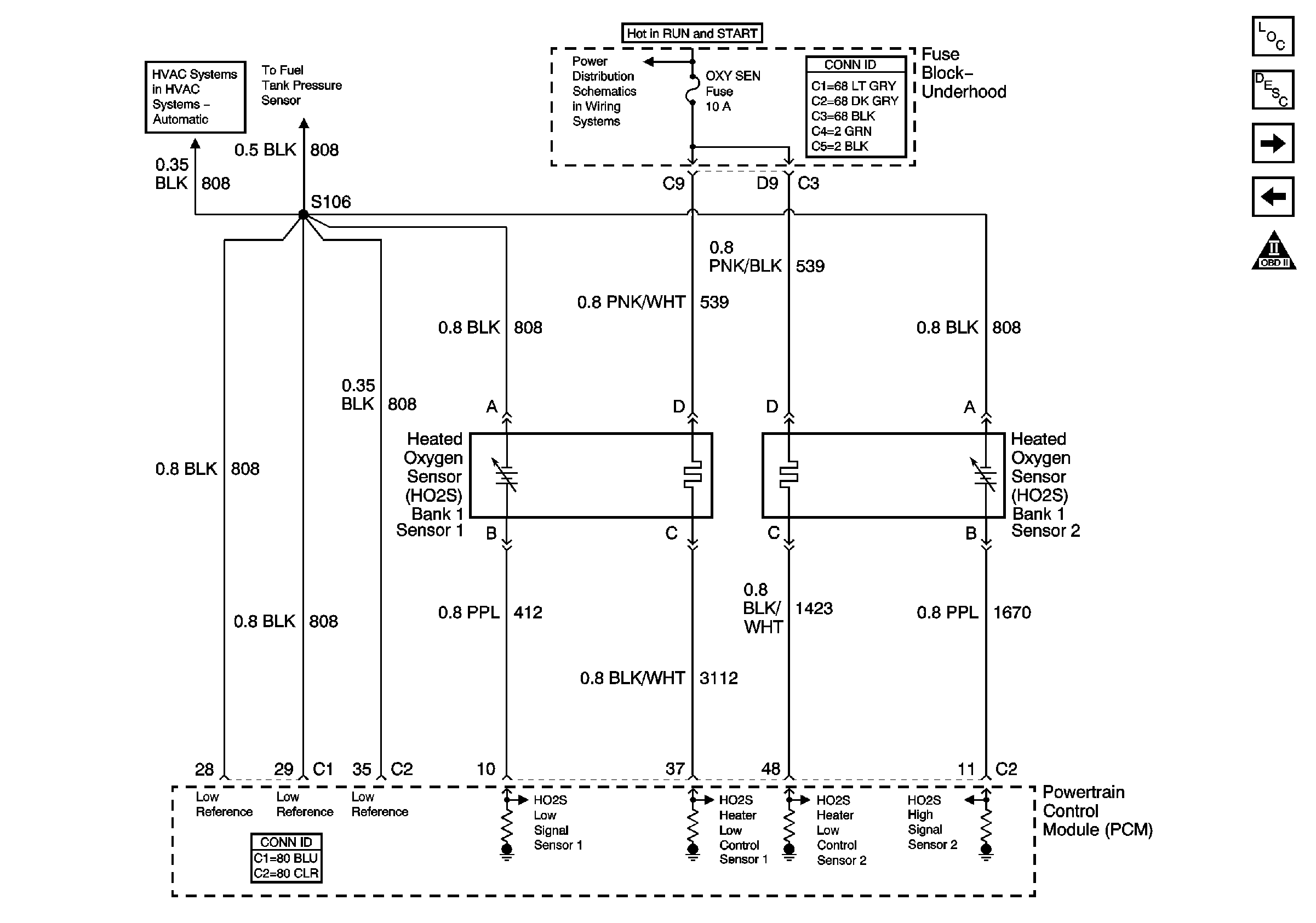
|
| Figure 9: |
EVAP Canister Purge Valve, IAC, and MAF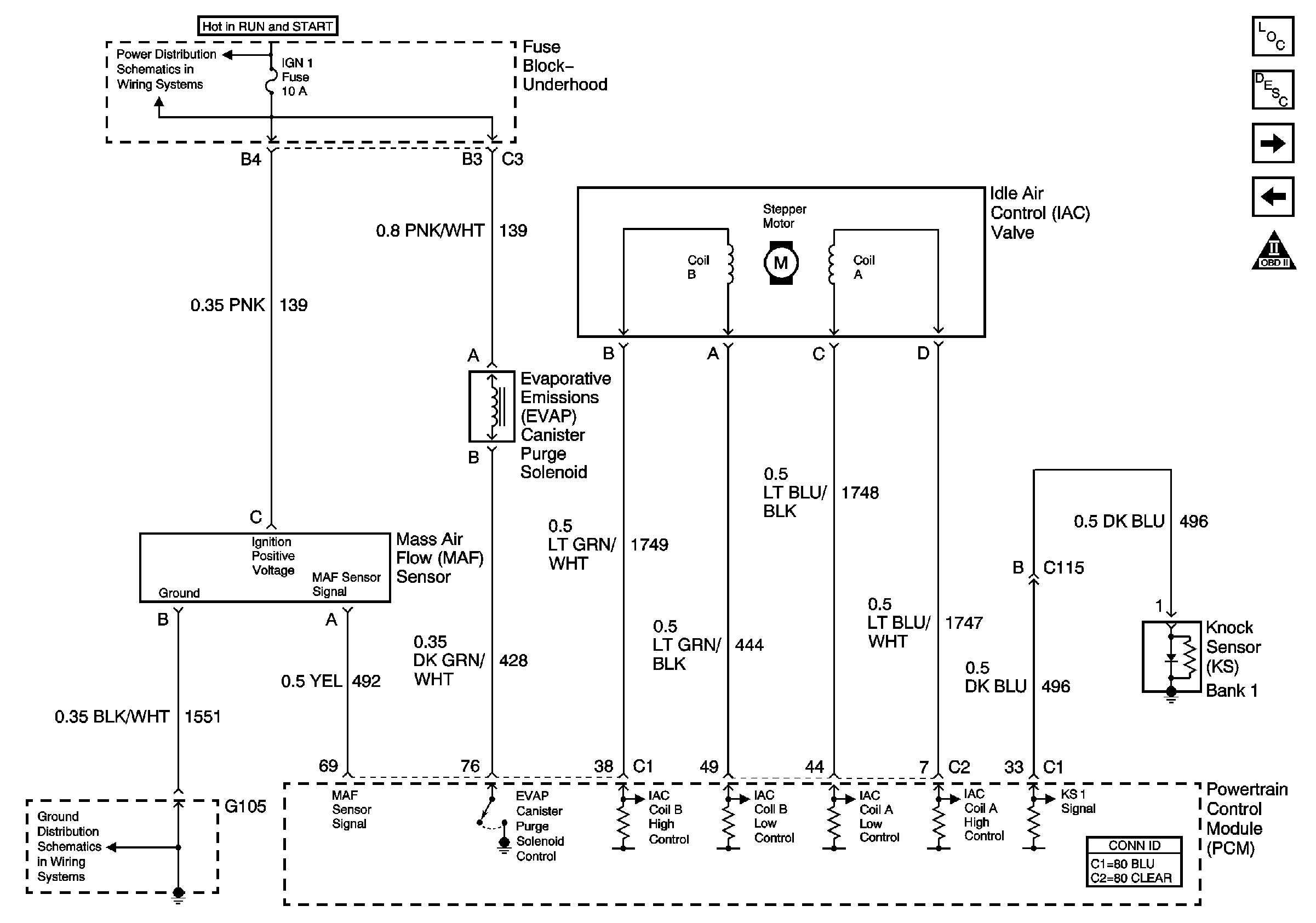
|
| Figure 10: |
AIR Pump and Controls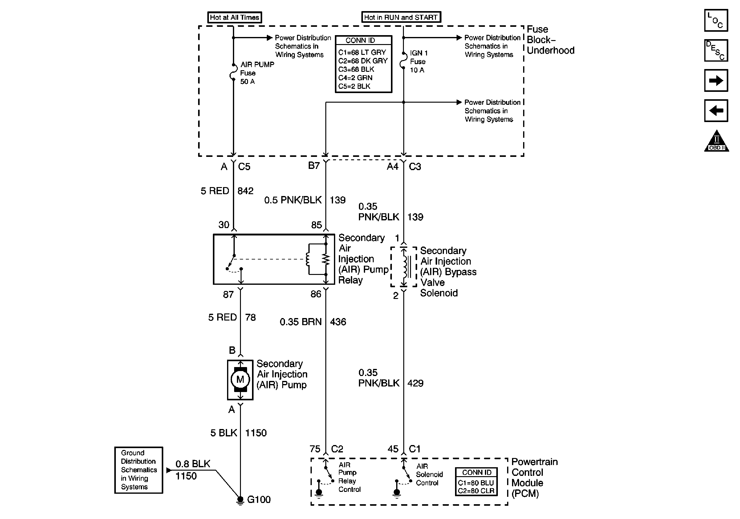
|
| Figure 11: |
PCM Controls (1 of 2)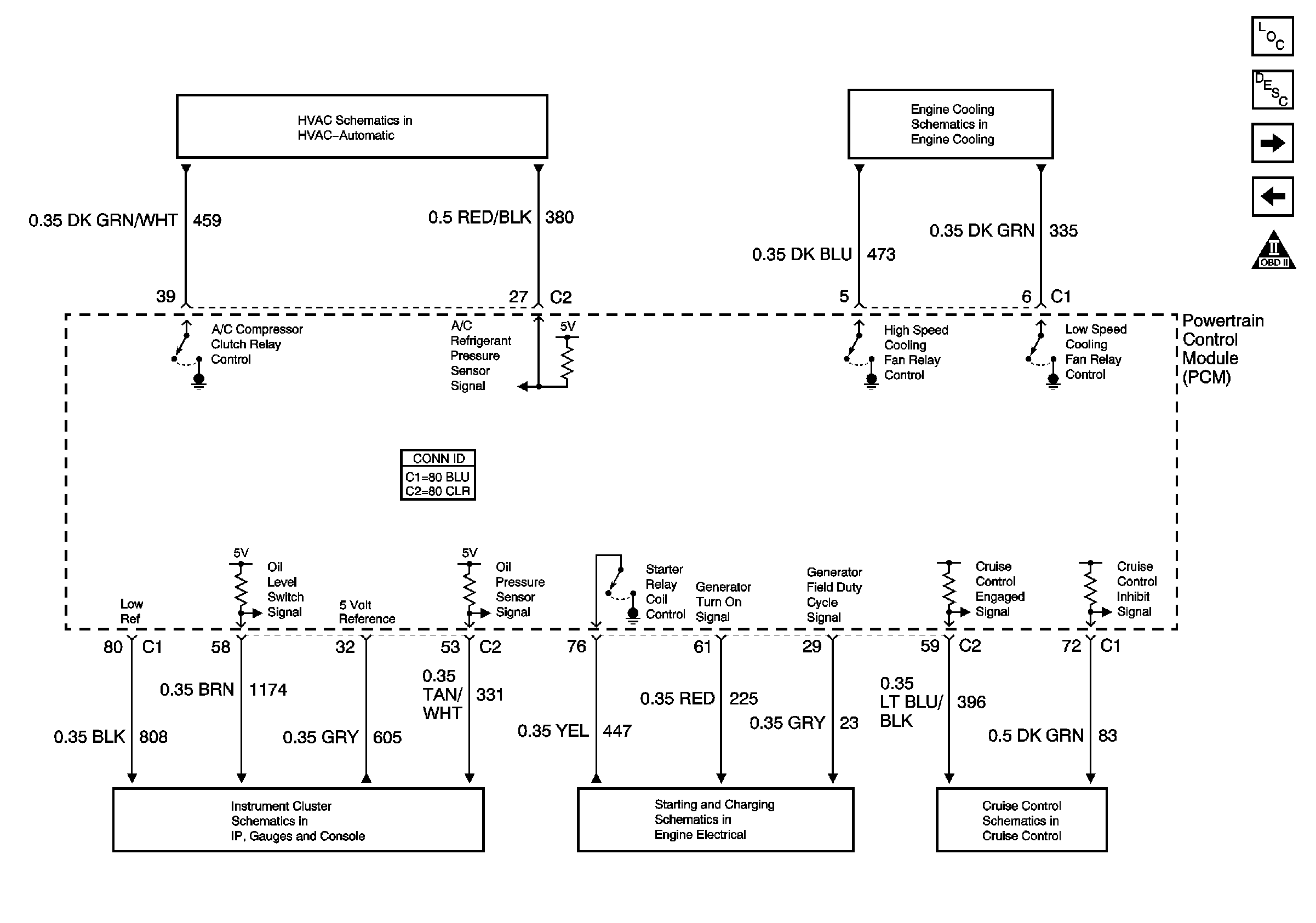
|
| Figure 12: |
PCM Controls (2 of 2)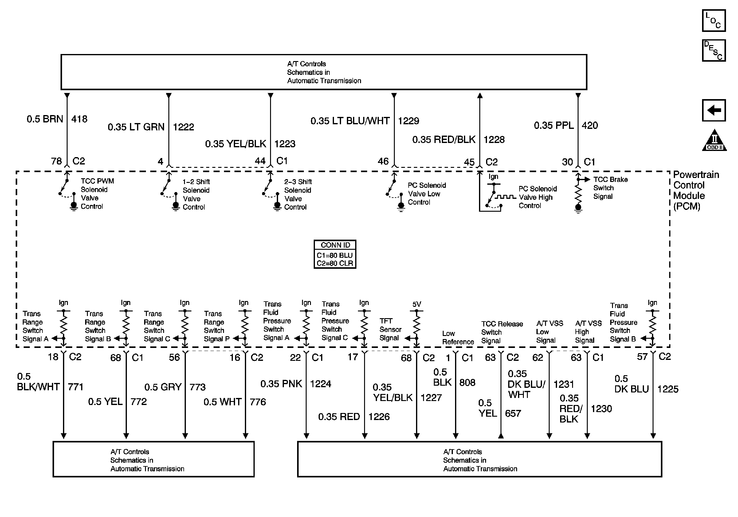
|
