Important: Ensure that the crankshaft is in the TDC position using the J 43032
.
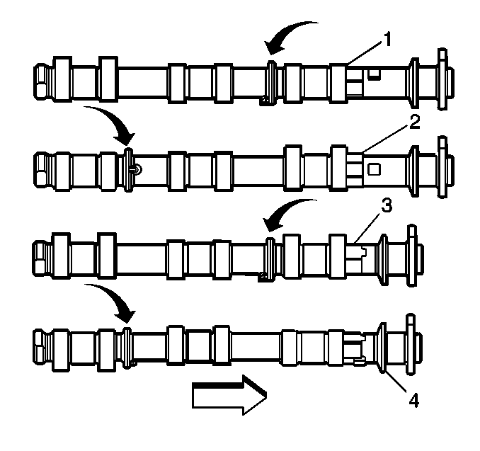
- Select the proper camshaft for the particular installation location.
The left cylinder head camshafts (1, 2) are longer than those for the
right cylinder head (3, 4). However, both sets of camshafts share the
same placement of identification rings. The ring placement is defined as follows:
| 1.1. | The identification ring for the intake camshafts (1, 3)
is located between the first and second sets of lobes. |
| 1.2. | The identification ring for the exhaust camshafts (2, 4)
is located between the second and third sets of lobes. |
- Apply a liberal amount
of lubricant GM P/N United States 12345501, GM P/N Canada 992704,
or equivalent to the camshaft journals and the cylinder head camshaft carriers.
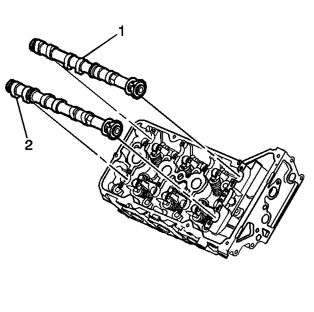
- Place the intake (1) and exhaust (2) camshafts in
position in the cylinder head.
Important: Ensure each valve rocker arm is properly aligned to the valve tip, the
valve lifter and the camshaft lobe. Inspect the alignment prior to and after
the camshaft caps are tightened to specifications.
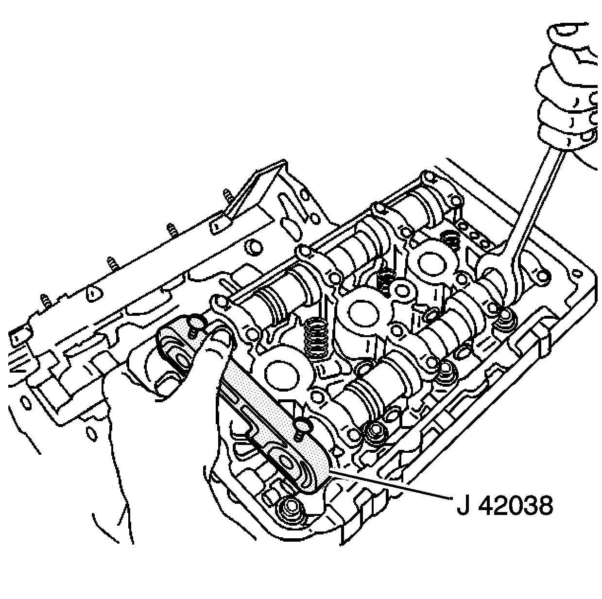
- Position the camshaft lobes in a neutral position with the front notch
for the camshaft sprocket drive pins near the top of their rotation and the
rear flats of the camshaft near the installation position of the J 42038
.
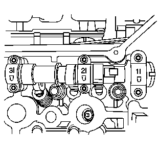
- Observe the markings on
the bearing caps. Each bearing cap is marked in order to identify its location.
The markings have the following meanings:
| • | The raised feature must always be oriented toward the outboard
side of the engine. |
| • | The I indicates the intake camshaft. |
| • | The E indicates the exhaust camshaft. |
| • | The number indicates the journal position from the front of the
engine. |
- Apply a liberal amount of lubricant GM P/N United
States 12345501, GM P/N Canada 992704, or equivalent
to the camshaft bearing caps.
- Install the camshaft bearing
thrust caps in the first journal of each camshaft. The thrust caps are wider
than the others and have machined undercuts not present on the other caps.
Ensure that the orientation marking is closest to the engine outboard side.
- Install the remaining bearing caps with their orientation mark
closest to the engine outboard side.
- Hand start all the camshaft bearing cap bolts.
Notice: Use the correct fastener in the correct location. Replacement fasteners
must be the correct part number for that application. Fasteners requiring
replacement or fasteners requiring the use of thread locking compound or sealant
are identified in the service procedure. Do not use paints, lubricants, or
corrosion inhibitors on fasteners or fastener joint surfaces unless specified.
These coatings affect fastener torque and joint clamping force and may damage
the fastener. Use the correct tightening sequence and specifications when
installing fasteners in order to avoid damage to parts and systems.
- Tighten the camshaft bearing cap bolts.
Tighten
- Tighten the camshaft bearing cap bolts to 8 N·m (71 lb in).
- Tighten the camshaft bearing cap bolts an additional 22 degrees
using theJ 36660-A
.
Important: Ensure each valve rocker arm is properly aligned to the valve tip, the
valve lifter and the camshaft lobe. Inspect the alignment prior to and after
the camshaft caps are tightened to specifications.
Important: There should be no need to rotate the camshaft more then 10 degrees.
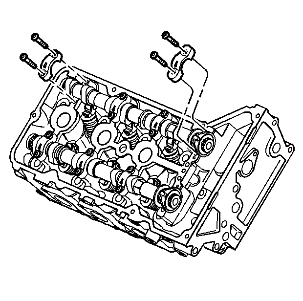
- Using the hex cast into the camshaft, rotate the camshaft so the rear
camshaft flat is facing the cylinder head in order to install the J 42038
.
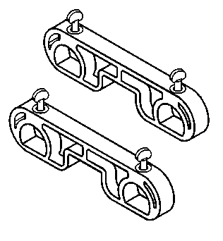
- Install the J 42038
at the rear of the cylinder head.
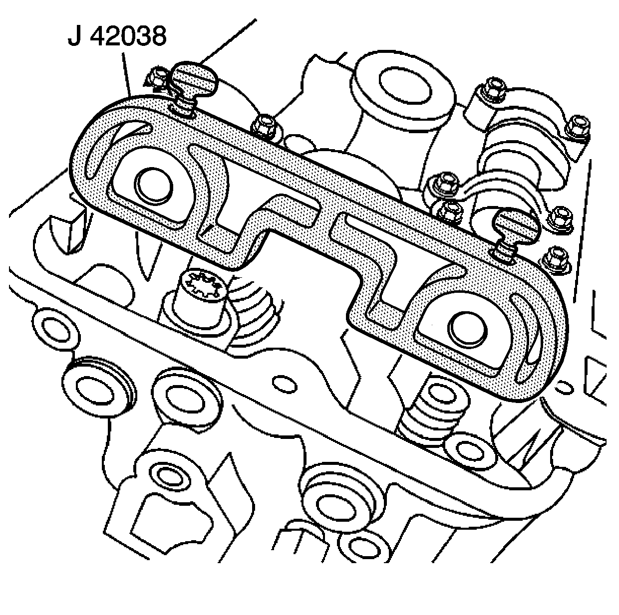
Important: All camshafts must be locked in place before installation of the secondary
timing chains.
- Ensure that the J 42038
is fully seated and locked onto the camshafts.
