Ignition Coil Module Installation - Right Side w/o RPO NC1
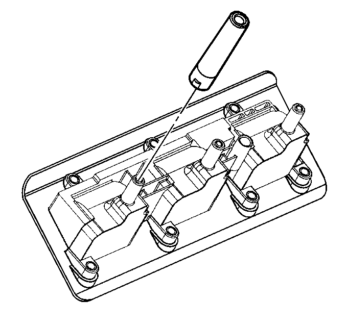
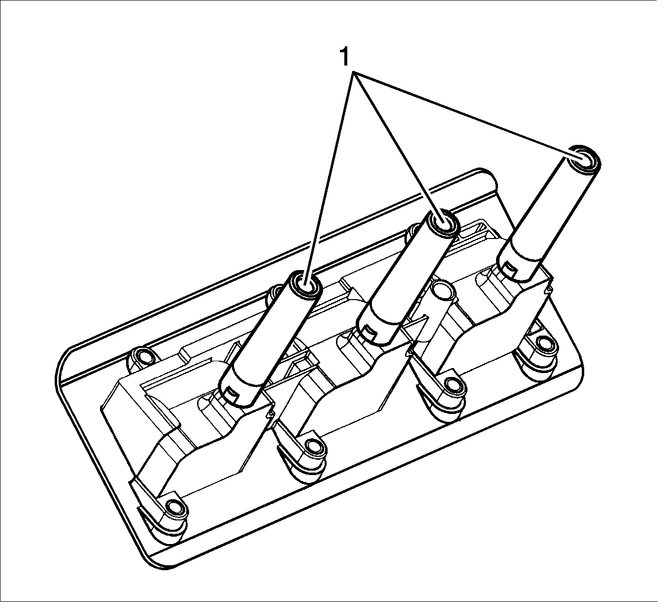
- Press the spark plug boots onto the ignition coil assembly.
- Apply a small amount of dielectric grease GM P/N 12345579, (Canadian P/N 1974984), to each spark plug boot (1) of the ignition coil assembly.
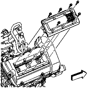
- Lower the ignition coil assembly into the camshaft cover valley. DO NOT damage the ignition coil assembly's perimeter seal.
- Install the ignition coil assembly bolts.
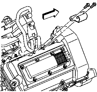
- Install the fuel injector sight shield bracket.
- Install the fuel injector sight shield bracket bolts.
Notice: Use the correct fastener in the correct location. Replacement fasteners must be the correct part number for that application. Fasteners requiring replacement or fasteners requiring the use of thread locking compound or sealant are identified in the service procedure. Do not use paints, lubricants, or corrosion inhibitors on fasteners or fastener joint surfaces unless specified. These coatings affect fastener torque and joint clamping force and may damage the fastener. Use the correct tightening sequence and specifications when installing fasteners in order to avoid damage to parts and systems.
Tighten
Tighten the ignition coil assembly bolts to 9 N·m (80 lb in).
Tighten
Tighten the fuel injector sight shield bracket bolts to 8 N·m (71 lb in).
Ignition Coil Module Installation - Right Side with RPO NC1
- Press the spark plug boots onto the ignition coil assembly.
- Apply a small amount of dielectric grease GM P/N 12345579, (Canadian P/N 1974984), to each spark plug boot (1) of the ignition coil assembly.
- Lower the ignition coil assembly into the camshaft cover valley. DO NOT damage the ignition coil assembly's perimeter seal.
- Install the ignition coil assembly bolts.
- Install the A.I.R. vacuum control solenoid/fuel injector sight shield bracket.
- Install the A.I.R. vacuum control solenoid/fuel injector sight shield bracket bolts.


Notice: Use the correct fastener in the correct location. Replacement fasteners must be the correct part number for that application. Fasteners requiring replacement or fasteners requiring the use of thread locking compound or sealant are identified in the service procedure. Do not use paints, lubricants, or corrosion inhibitors on fasteners or fastener joint surfaces unless specified. These coatings affect fastener torque and joint clamping force and may damage the fastener. Use the correct tightening sequence and specifications when installing fasteners in order to avoid damage to parts and systems.
Tighten
Tighten the ignition coil assembly bolts to 9 N·m (80 lb in).
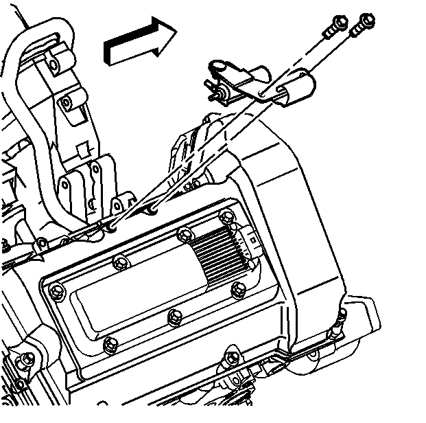
Tighten
Tighten the A.I.R. vacuum control solenoid/fuel injector sight shield bracket bolts to 8 N·m (71 lb in).
