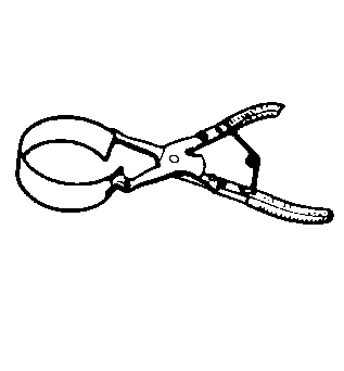
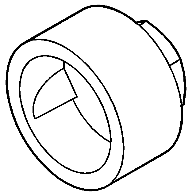
Tools Required
| • | J 29789 Piston Ring Compressor |
| • | J 39946 Crankshaft Socket - 4.0L and 4.6L |
| • | J 36660-A Torque Angle Meter |
Piston and Connecting Rod Assembly Procedure
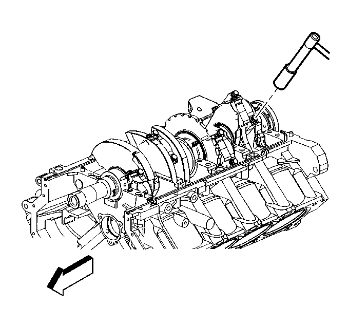
- Rotate the crankshaft using the J 39946 in order to align the crankshaft connecting rod journal being serviced to BDC.
- Liberally lubricate the cylinder walls, piston rings and piston skirts with clean engine oil.
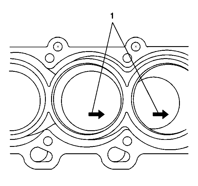
- Select the correctly numbered piston/connecting rod assembly for the cylinder. An arrow showing proper piston orientation is located on the top of the piston.
- Compress the piston rings using the J 29789 or equivalent.
- Using both hands, slowly guide the piston and connecting rod assembly into the cylinder from the top and bottom of the cylinder. DO NOT allow the connecting rod to contact the cylinder wall.
- When the piston ring compressor contacts the deck surface, gently tap the piston into the cylinder using the handle end of a dead-blow hammer. Guide the connecting rod onto the crankshaft bearing journal while taping the piston into the cylinder.
Important: Connecting rod bearings that have been used in a running engine, must be replaced with NEW connecting rod bearings for reassembly.
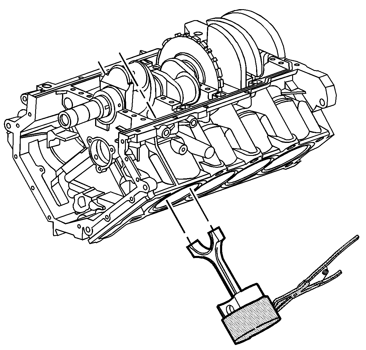
Important: Extreme care must be exercised when installing the piston and connecting rod in order to be sure the rod does not scrape or nick the cylinder bore or the crankshaft surfaces.
Connecting Rod Bearing Clearance Measurement Procedure
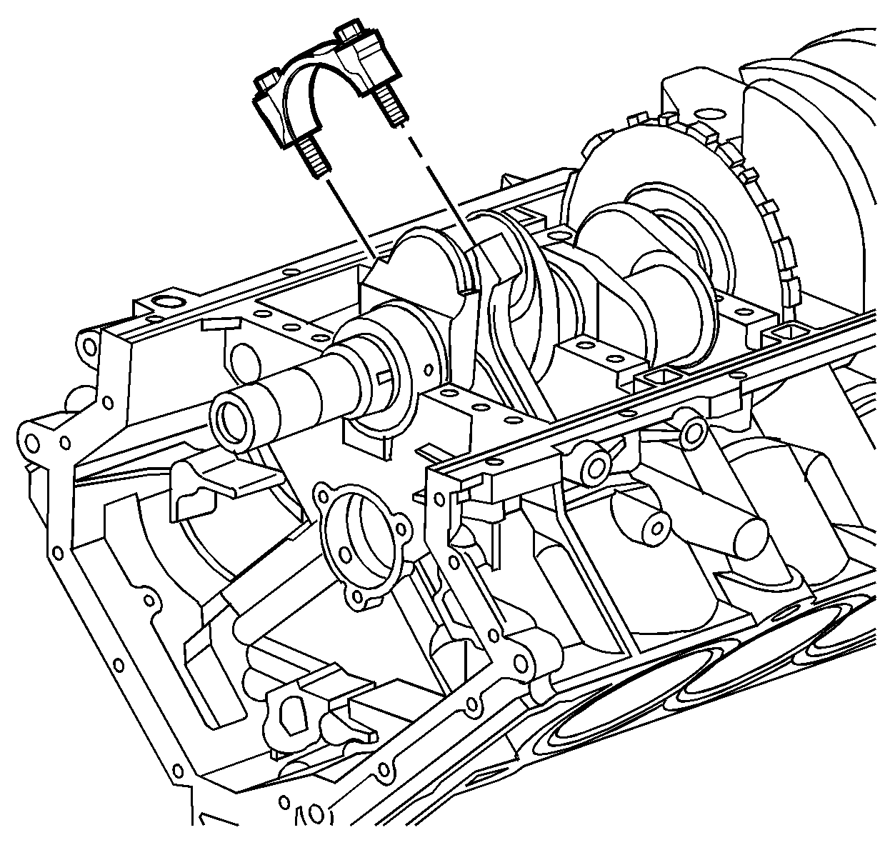
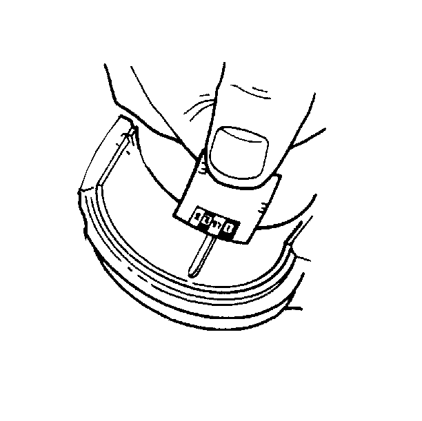
- Before final assembly it is important to check the clearance of the new connecting rod bearings.
- Place a length of fresh, room temperature plastic gaging material all the way across all the connecting rod bearing journal.
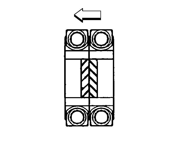
- Install the connecting rod end cap on its original connecting rod making sure the bearing lock tangs are aligned on the same side of the rod.
- When properly installed, the connecting rod bearing cap notches should be paired, as shown, on the crankpin.
- Lubricate connecting rod bolts with engine oil and install in the connecting rod.
- Loosen the connecting rod bolts until the torque reading is zero.
- Re-tighten the connecting rod bolts.
- Allow the assembly to sit for at least two minutes.
- Remove the connecting rod cap bolts.
- Remove the connecting rod cap.
- Determine the connecting rod bearing clearance by comparing the width of the flattened plastic gaging material at its widest point with the graduation on the gaging material container.
- Compare the measurements with the engine mechanical specifications. Refer to Engine Mechanical Specifications .
- If the new bearings do not provide the proper crankshaft to bearing clearance, re-measure the crankshaft journals for the correct specified size and check to make sure you have the correct new bearings. If the crankshaft journals are incorrectly sized, replace the crankshaft. No crankshaft machining is permitted and undersized bearings are not available.
- Clean the plastic gaging material from the connecting rod bearing and crankshaft connecting rod bearing journal using a soft lint-free cloth.
Important: Connecting rod bearings that have been used in a running engine, must be replaced with NEW connecting rod bearings for reassembly.
Notice: Use the correct fastener in the correct location. Replacement fasteners must be the correct part number for that application. Fasteners requiring replacement or fasteners requiring the use of thread locking compound or sealant are identified in the service procedure. Do not use paints, lubricants, or corrosion inhibitors on fasteners or fastener joint surfaces unless specified. These coatings affect fastener torque and joint clamping force and may damage the fastener. Use the correct tightening sequence and specifications when installing fasteners in order to avoid damage to parts and systems.
Important: Reuse the old connecting rod bolts ONLY for measuring the connecting rod bearing clearance.
Tighten
Tighten the connecting rod bolts to 30 N·m (22 lb ft).
| 7.1. | First Pass |
Tighten
Tighten the connecting rod bolts to 25 N·m (18 lb ft).
| 7.2. | Final Pass |
Tighten
Tighten the connecting rod bolts an additional 110 degrees using
the J 36660-A
.
Connecting Rod Final Assembly Procedure
- Back the connecting rod away from the crankshaft in order to allow for lubricant application.
- Coat the crankshaft connecting rod bearing journal and installed connecting rod bearings with GM crankshaft prelube GM P/N 1052367, (Canadian P/N 992869), or equivalent.
- Guide the connecting rod onto the crankshaft connecting rod bearing journal.
- Install the connecting rod end cap on its original connecting rod making sure the bearing lock tangs are aligned on the same side of the rod.
- When properly installed, the connecting rod bearing cap notches should be paired, as shown, on the crankpin.
- Lubricate the NEW connecting rod bolts with engine oil and install in the connecting rod.
- Loosen the connecting rod bolts until the torque reading is zero.
- Re-tighten the connecting rod bolts.
- During and after installation, check to make sure each piston is positioned properly in the correct cylinder. The locating arrow on the top each piston (1) must be pointing toward the front of the engine.
- Repeat these procedures for the piston/connecting rod assembly that is using the common crankshaft connecting rod journal.
- Measure the connecting rod side clearance between the two connecting rods that share the common crankshaft connecting rod journal.
- Compare the measurements with the engine mechanical specifications. Refer to Engine Mechanical Specifications .
- If the connecting rods do not provide the proper crankshaft side clearance inspect for the following conditions:
- Repeat these procedures for the remaining piston/connecting rod assemblies using the J 39946 in order to rotate the crankshaft.
Notice: Use the correct fastener in the correct location. Replacement fasteners must be the correct part number for that application. Fasteners requiring replacement or fasteners requiring the use of thread locking compound or sealant are identified in the service procedure. Do not use paints, lubricants, or corrosion inhibitors on fasteners or fastener joint surfaces unless specified. These coatings affect fastener torque and joint clamping force and may damage the fastener. Use the correct tightening sequence and specifications when installing fasteners in order to avoid damage to parts and systems.
Important: DO NOT reuse the old connecting rod bolts.
Tighten
Tighten the NEW connecting rod bolts to 30 N·m (22 lb ft).
| 8.1. | First Pass |
Tighten
Tighten the connecting rod bolts to 25 N·m (18 lb ft).
| 8.2. | Final Pass |
Tighten
Tighten the connecting rod bolts an additional 110 degrees using
theJ 36660-A
.
| • | If the clearance is too tight, ensure the connecting rods are not binding and can slide parallel to the crankpin. Re-measure the connecting rod widths for the correct specified size. If the connecting rods are incorrectly sized, replace the connecting rods. |
| • | If the clearance is too loose, re-measure the connecting rod widths for the correct specified size. If the connecting rods are incorrectly sized, replace the connecting rods. |
