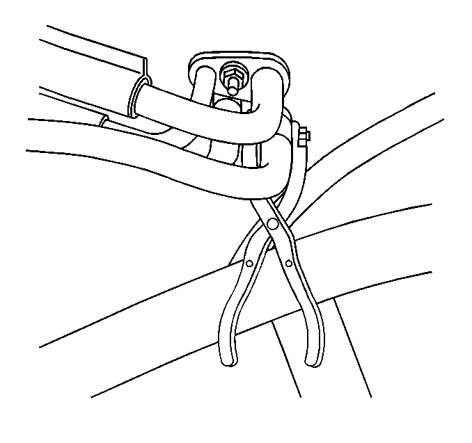
Tools Required
| • | J 38185 Hose Clamp Pliers |
| • | J 39400 Halogen Leak Detector |
Removal Procedure
- Recover the refrigerant. Refer to Refrigerant Recovery and Recharging .
- Drain the cooling system. Refer to Cooling System Draining and Filling in Engine Cooling.
- Using theJ 38185 loosen the clamp.
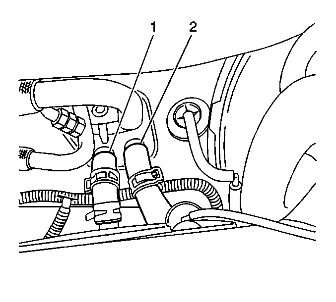
- Remove the heater hoses (1, 2) from the heater core.
- Remove the left side sound insulator. Refer to Instrument Panel Insulator Panel Replacement - Left Side in Instrument Panel, Gages and Console.
- Remove the right side sound insulator. Refer to Instrument Panel Insulator Panel Replacement - Right Side in Instrument Panel, Gages and Console.
- Remove the console assembly. Refer to Front Floor Console Replacement in Instrument Panel, Gages and Console.
- Remove the lower dash support bracket.
- Remove the auxiliary air distribution duct adapter.
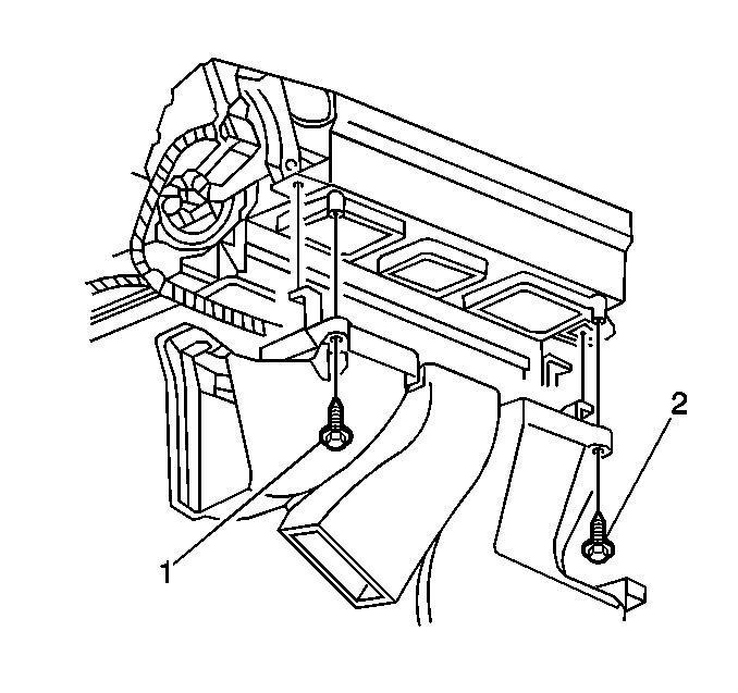
- Remove the air distributor duct screws (1, 2). Due to the difficulty in the removal of the right side screw (2), it will not be necessary to install upon reassembly.
- Remove the air distributor duct.
- Remove the heater core heat shield screws.
- Remove the heater core heat shield.
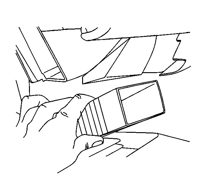
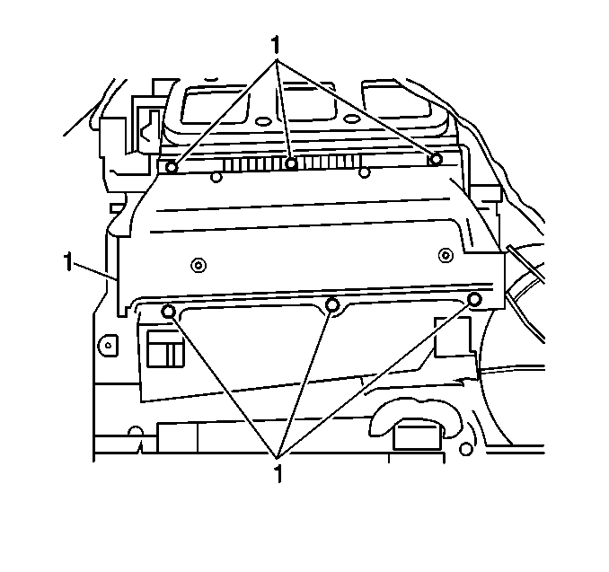
- Remove the heater core cover screws (1).
- Remove the heater core cover.
- Remove the retaining screw and strap from the heater core.
- Remove the heater core.
Installation Procedure
- Install the heater core into the HVAC module using the attaching straps and screws.
- Install the heater core cover.
- Ensuring the seals at the front of dash are in the proper positions, install the heater core cover screws.
- Install the heater core heat shield and screws (1).
- Install the air distributor duct and the left screw (1). Ensure the right tab is seated properly.
- Install the auxiliary air distribution duct adapter.
- Install the lower dash support bracket.
- Install the console assembly. Refer to Front Floor Console Replacement in Instrument Panel, Gages and Console.
- Install the left side sound insulator. Refer to Instrument Panel Insulator Panel Replacement - Left Side in Instrument Panel, Gages and Console.
- Install the right side sound insulator. Refer to Instrument Panel Insulator Panel Replacement - Right Side in Instrument Panel, Gages and Console.
- Connect the heater hoses to the pipes.
- Using theJ 38185 reposition the clamp.
- Fill the cooling system. Refer to Cooling System Draining and Filling in Engine Cooling.
- Recharge the A/C system. Refer to Refrigerant Recovery and Recharging .
Notice: Use the correct fastener in the correct location. Replacement fasteners must be the correct part number for that application. Fasteners requiring replacement or fasteners requiring the use of thread locking compound or sealant are identified in the service procedure. Do not use paints, lubricants, or corrosion inhibitors on fasteners or fastener joint surfaces unless specified. These coatings affect fastener torque and joint clamping force and may damage the fastener. Use the correct tightening sequence and specifications when installing fasteners in order to avoid damage to parts and systems.
Tighten
Tighten the screw to 1.4 N·m (12 lb in).
Tighten
Tighten the screws to 1.4 N·m (12 lb in).

Tighten
Tighten the screws to 1.4 N·m (12 lb in).

Tighten
Tighten the screw to 1.4 N·m (12 lb in).

