Removal Procedure
- Disconnect the negative battery cable.
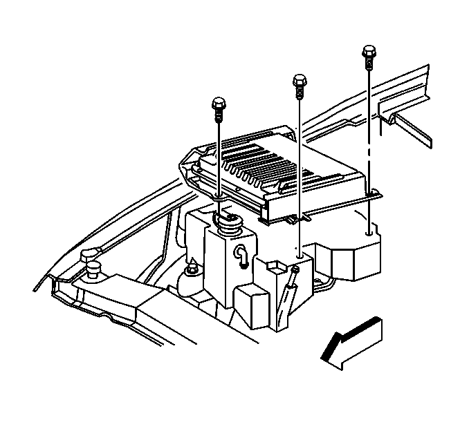
- Remove the VCM bracket bolts.
- Lift the inside edge of the VCM bracket until the bottom of the bracket can clear the A/C accumulator.
- Slide the VCM bracket over the A/C accumulator.
- Continue sliding the VCM bracket until the fender side of the bracket is no longer underneath the fender lip.
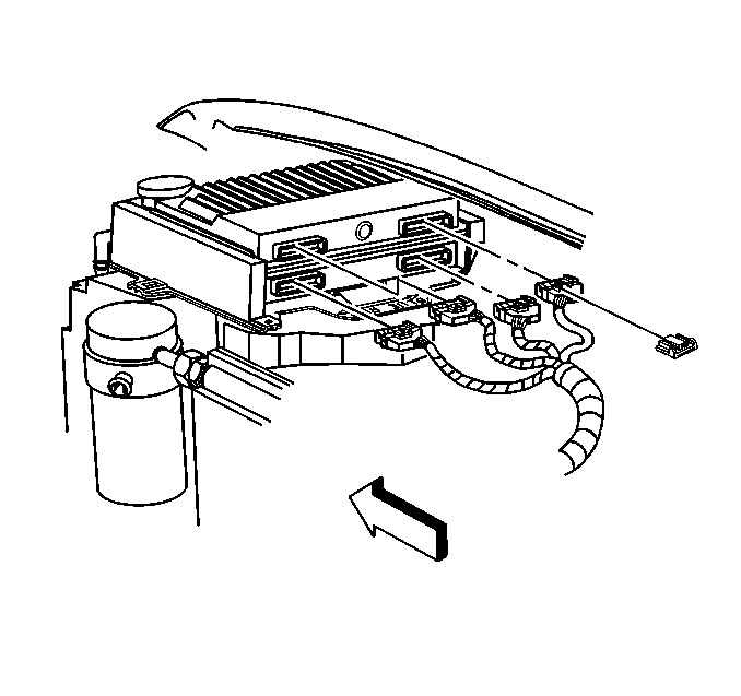
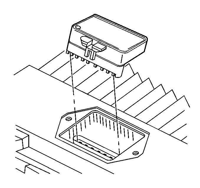
- Remove the retainer clips and VCM connectors.
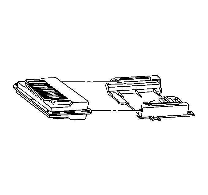
- Remove the VCM from the VCM bracket.
- Steps 8-10 are only necessary for a VCM replacement:
- Remove the VCM access cover.
- Gently pinch the retaining clip and pull upward to remove the Electronic Spark Control module/PROM.
Caution: Unless directed otherwise, the ignition and start switch must be in the OFF or LOCK position, and all electrical loads must be OFF before servicing any electrical component. Disconnect the negative battery cable to prevent an electrical spark should a tool or equipment come in contact with an exposed electrical terminal. Failure to follow these precautions may result in personal injury and/or damage to the vehicle or its components.
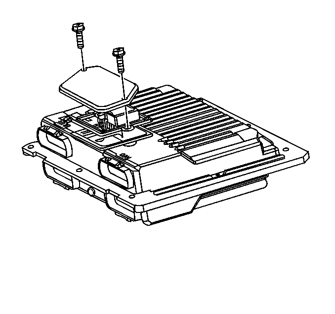
Remove the access cover screws.
Important: Since the module will be used in the replacement VCM, place the module in an area where it will not be damaged.
Installation Procedure
Important: Ensure that the VCM being installed is the original VCM, or that the replacement VCM service number is identical to the original VCM service number.
Steps 1-4 are only necessary for a new VCM installation:
- Align the notches of the Electronic Spark Control module/PROM with the notches in the Electronic Spark Control module/PROM socket.
- Install the Electronic Spark Control module/PROM in the Electronic Spark Control module/PROM socket.
- Install the access cover on the VCM.
- Install the access cover screws.
- Insert the VCM into the VCM bracket.
- Connect the VCM connectors and retainer clips.
- Insert the VCM bracket at an angle whereby the fender side of the bracket is positioned underneath the fender lip.
- Push the VCM bracket underneath the lip until the inside edge of the bracket clears the A/C accumulator.
- Install the VCM bracket bolts.
- Connect the negative battery cable.
- If the Electronic Spark Control module/PROM was replaced, then program the VCM.
Notice: In order to prevent possible electrostatic discharge (ESD) damage to the VCM, do not touch the connector pins or soldered components on the circuit board.
Important: Press only on the ends of the Electronic Spark Control module/PROM. Gently press on the Electronic Spark Control module/PROM until it is firmly seated in the socket. Listen for the click.
Notice: Use the correct fastener in the correct location. Replacement fasteners must be the correct part number for that application. Fasteners requiring replacement or fasteners requiring the use of thread locking compound or sealant are identified in the service procedure. Do not use paints, lubricants, or corrosion inhibitors on fasteners or fastener joint surfaces unless specified. These coatings affect fastener torque and joint clamping force and may damage the fastener. Use the correct tightening sequence and specifications when installing fasteners in order to avoid damage to parts and systems.
Tighten
Tighten the access cover screws to 4.4-5.2 N·m (39-46 lb in).
Ensure that the VCM is fully seated, so that the snap retainer is up into its normal position and is retaining the module.
Notice: Use the correct fastener in the correct location. Replacement fasteners must be the correct part number for that application. Fasteners requiring replacement or fasteners requiring the use of thread locking compound or sealant are identified in the service procedure. Do not use paints, lubricants, or corrosion inhibitors on fasteners or fastener joint surfaces unless specified. These coatings affect fastener torque and joint clamping force and may damage the fastener. Use the correct tightening sequence and specifications when installing fasteners in order to avoid damage to parts and systems.
Tighten
Tighten the bolts to 9-11 N·m (80-97 lb in).
Important: The MIL, antilock and brake lamps will continue to be enabled until the VCM is programmed. Once the programming is complete, the lamps will turn off and normal operation will occur.
VCM Programming
- Take the following steps in order to set-up for programming the VCM (EEPROM) .
- Refer to an updated Techline terminal and follow the user's instructions for VCM programming.
- If the VCM fails to program, do the following functions:
- For a functional check, perform the Powertrain On-Board Diagnostic (OBD) System Check.
| • | The battery is fully charged. |
| • | The ignition is ON. |
| • | The Data Link Connector (DLC) is secure. |
| • | Check all the VCM connections. |
| • | Check the ITCS terminal and equipment for the latest software version. |
| • | Try again to program the VCM. If the programming fails again, replace the VCM. |
