Removal Procedure
- Disconnect the harness from the brake fluid reservoir.
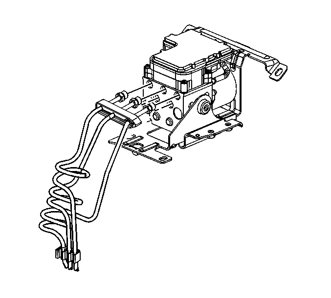
- Remove the plastic clip holding the brake pipes together, If equipped
- Disconnect the front brake pipe from the brake modulator assembly. Refer to Brake Pressure Modulator Valve Replacement in Antilock Brake System.
- Raise the vehicle. Refer to Lifting and Jacking the Vehicle in General Information.
- Remove both front tire and wheel assembly. Refer to Tire and Wheel Removal and Installation in Tires and Wheels.
- Disconnect the brake pipe from the brake hose.
- Remove the brake pipe.

Important: Do not remove the brake modulator assembly from vehicle.

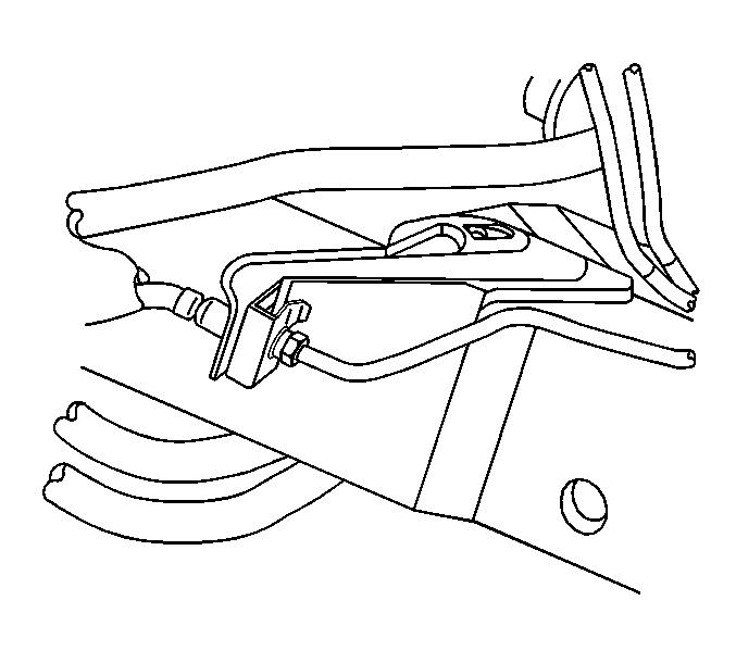
| 6.1. | If replacing the right front brake pipe, remove the brake pipe nut where the pipe from the ABS module and the right front pipe connect. It is located next to the front crossmember. |
| 6.2. | Remove the brake pipe from the clips attached to the front crossmember. |
Installation Procedure
Caution: Always use double-walled steel brake pipe when replacing brake pipes. The use of any other pipe is not recommended and may cause brake system failure. Carefully route and retain replacement brake pipes. Always use the correct fasteners and in the original location for replacement brake pipes. Failure to properly route and retain brake pipes may cause damage to the brake pipes and brake system resulting in personal injury.
- Install the brake pipe to the vehicle.
- Loosely install the brake pipe nut to the flex brake hose.
- Lower the vehicle.
- Loosely install the brake pipe nut to the brake modulator assembly.
- Check the routing of the brake pipe to make sure it does not rub against a moving part.
- Install the brake pipe nut to the brake modulator assembly. Refer to Brake Pressure Modulator Valve Replacement in Antilock Brake System.
- Install the brake Pipe nut to flex hose.
- Install the brake pipe clips.
- Connect the harness to brake fluid reservoir.
- Bleed the brake system. Refer to Hydraulic Brake System Bleeding or Antilock Brake System Automated Bleed Procedure .
- Install the front tire and wheel assembly. Refer to Tire and Wheel Removal and Installation in Tires and Wheels.
- Lower the vehicle.

| 2.1. | If installing the right front brake pipe, loosely install the brake pipe nut at the connection. |
| 2.2. | Check the routing of the brake pipe to make sure it does not rub against a moving part. |
Notice: Use the correct fastener in the correct location. Replacement fasteners must be the correct part number for that application. Fasteners requiring replacement or fasteners requiring the use of thread locking compound or sealant are identified in the service procedure. Do not use paints, lubricants, or corrosion inhibitors on fasteners or fastener joint surfaces unless specified. These coatings affect fastener torque and joint clamping force and may damage the fastener. Use the correct tightening sequence and specifications when installing fasteners in order to avoid damage to parts and systems.
| 2.3. | Install the brake pipe nut. |
Tighten
Tighten the brake pipe nut to 17 N·m (13 lb ft).

Tighten
Tighten the brake pipe nut to 30 N·m (22 lb ft).
