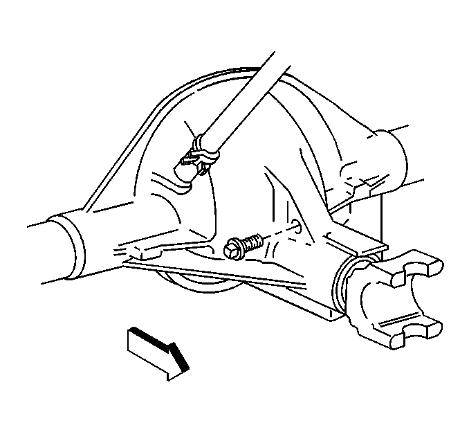
- Remove the rear axle fill plug.
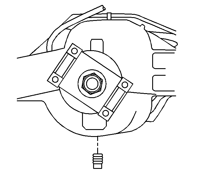
- Remove the rear axle drain plug.
- Drain the lubricant into a suitable container.
- Inspect the drain plug for excessive metal particle accumulation. This accumulation is symptomatic of extreme wear.
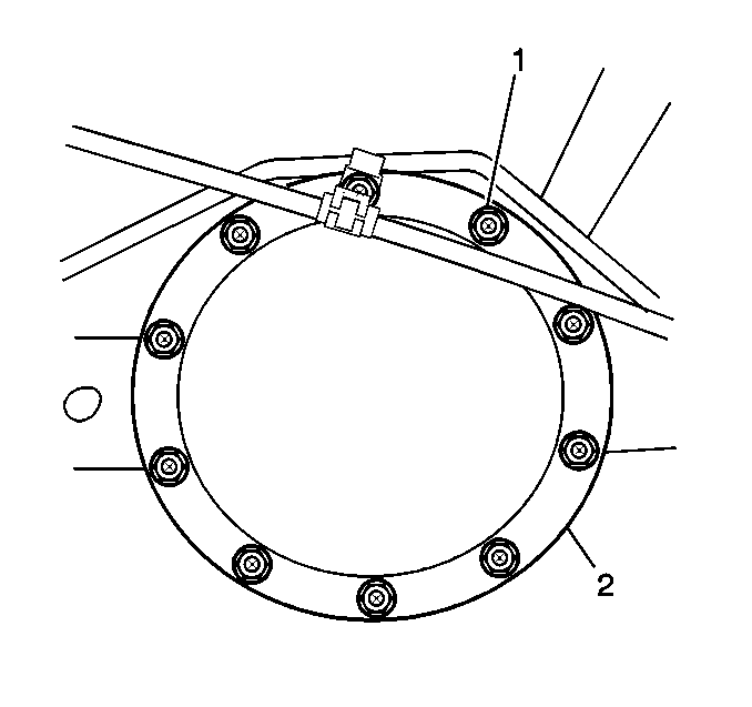
- Remove the rear axle housing cover bolts (1).
- Remove the rear axle housing cover (2) from the axle housing.
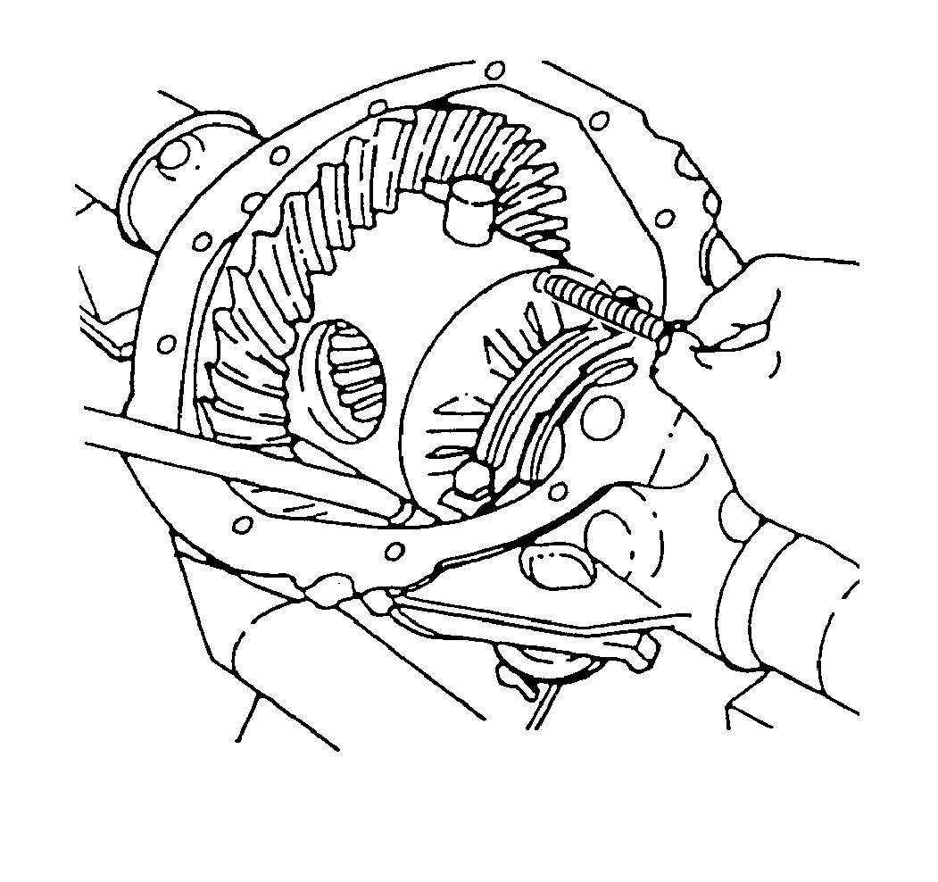
- Remove the pinion shaft locking bolt.
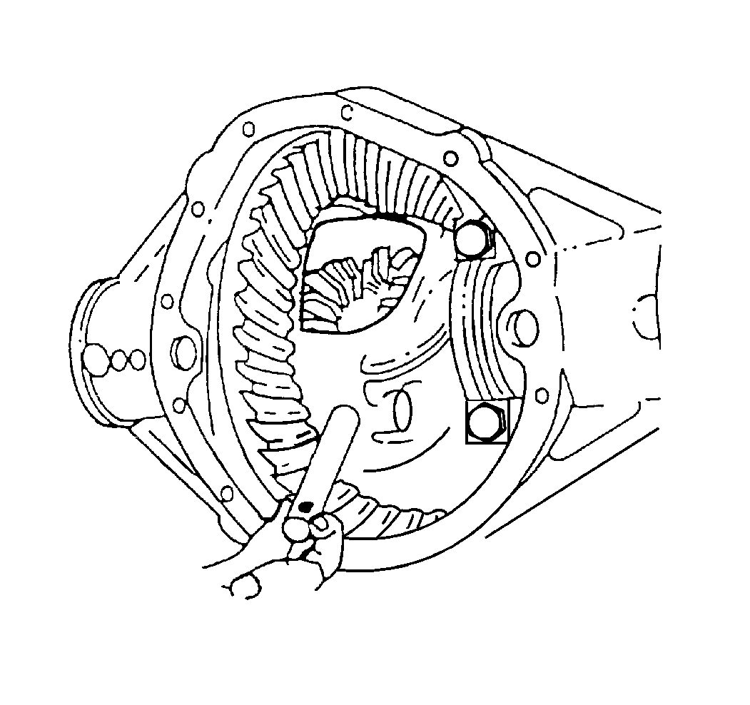
- On axles without a locking differential, remove the pinion shaft.
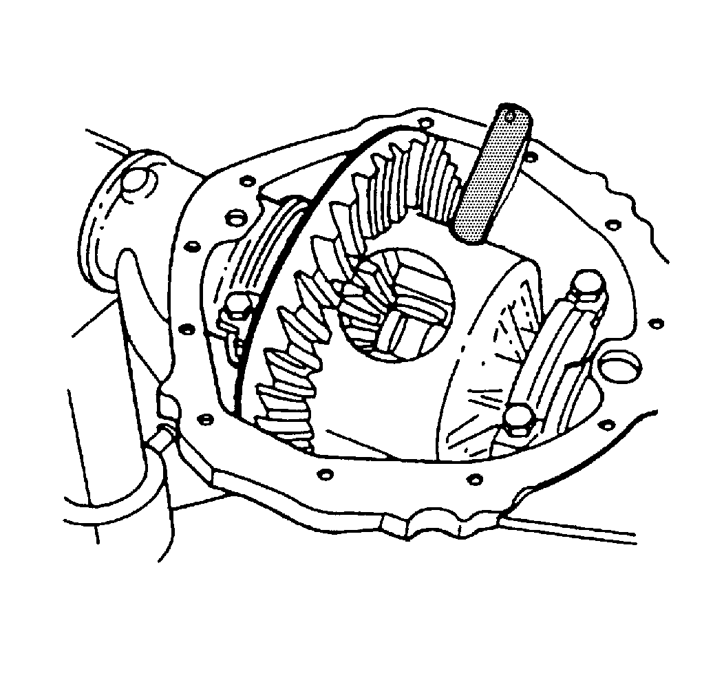
- On axles with a locking differential, remove the shaft part way. Rotate the case until the pinion shaft touches the housing.
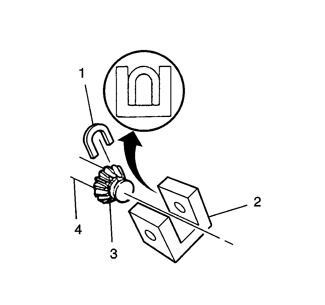
- On axles with a locking differential, use a screwdriver, or a similar tool, in order to enter the differential case and rotate the lock (1) until the lock aligns with the thrust block (2).
- Push the flange of the axle shaft toward the differential.
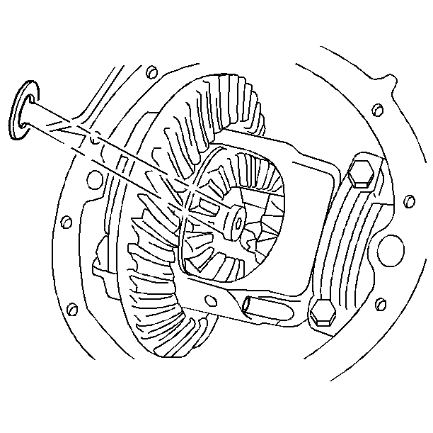
- Remove the lock from the button end of the axle shaft.
- Remove the axle shaft from the axle housing.
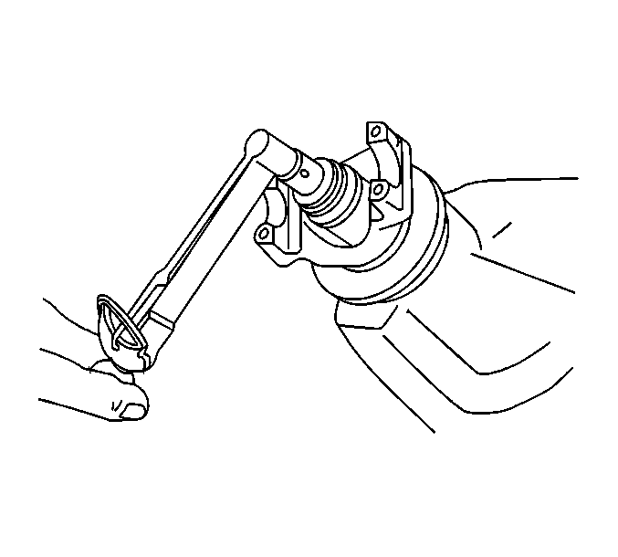
- Measure the amount of torque required to rotate the pinion. Use an inch-pound torque wrench. Record this measurement for reassembly. This will give the combined preload for the following components:
| • | The differential case bearings |
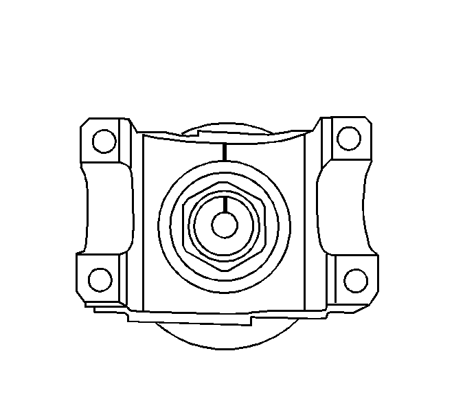
- Scribe an alignment mark between the pinion yoke and the pinion stem.
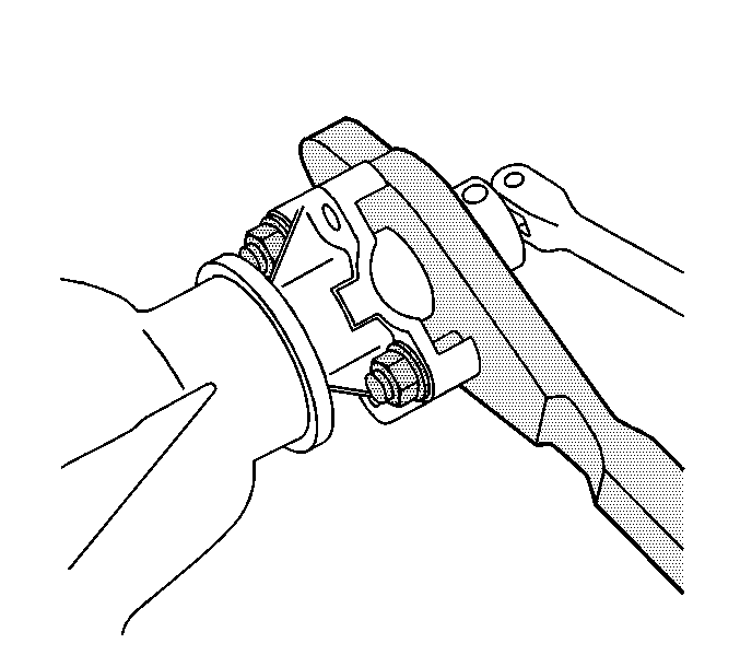
- Install the J 8614-01
as shown.
- Remove the pinion nut while holding the J 8614-01
.
- Remove the washer.
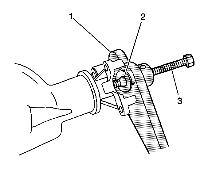
- Install the J 8614-2 (2) and the J 8614-3 (3) into the J 8614-01
(1) as shown.
- Remove the pinion yoke by turning the J 8614-3 (3) clockwise while holding the J 8614-01
(1).
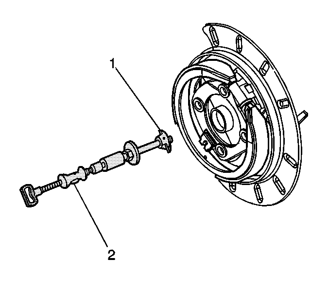
- Remove the axle shaft seal and the bearing from the axle shaft tube using the J 44685
(1) and the J 2619-01
(2).
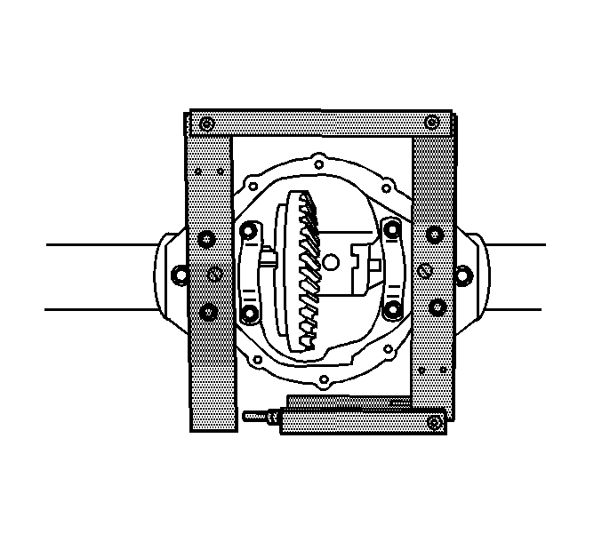
- Install the J 45222
to the axle housing as shown.
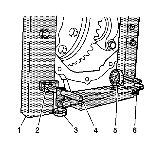
- Install the J 8001-1 (2), the J 8001-2 (3), the J 34178
(4, 6), and the J 8001-3 (5) as shown.
- Preload the J 8001-3 (5) approximately 3/4 of a turn clockwise.
- Rotate the indicator housing to align the indicator needle of the J 8001-3 (5) and the dial indicator face to ZERO.
- Spread the axle housing by turning the clevis screw of the J 34178
while observing the J 8001-3.
Spread the housing just enough to remove the differential assembly. Do not spread the housing more than 1.02 mm (0.040 in).
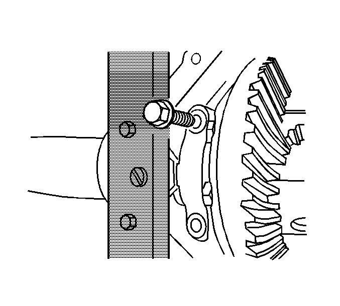
- Remove the bearing caps bolts and the caps. Mark the bearing caps left and right.
Caution: To prevent personal injury and/or component damage, support the differential
case when removing the case from the axle housing. If the case is not supported,
the differential case could fall and cause personal injury or damage to the
differential case.
Notice: When removing the differential case from the axle housing, do not damage
the cover gasket surface. If the cover gasket surface is damaged, lubricant
may leak from the axle and cause premature failure of the axle assembly.
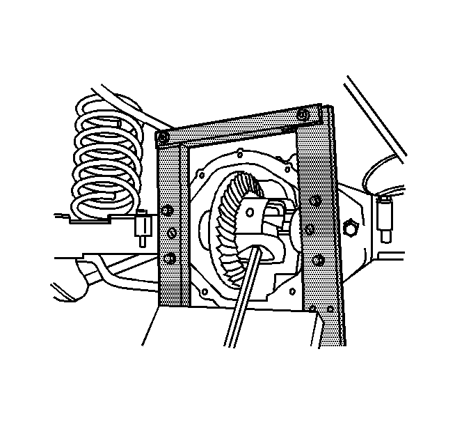
- Remove the differential from the axle housing using a pry bar and a block of wood.
- Remove the bearing cups, the shims, and the spacers as necessary.
Mark the cups and shims left and right and in the proper order as necessary. Place the cups and the shims with the bearing caps.
- Remove the J 8001-1, the J 8001-2, the J 34178
, and the J 8001-3.
- Remove the J 45222
.
- Remove the differential side bearings, if necessary. Refer to
Differential Side Bearings Replacement
.
- Remove the ring gear, if necessary. Refer to
Drive Pinion and Ring Gear Replacement
.
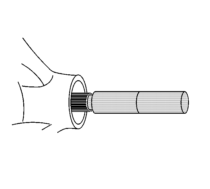
- Install the J 22536
as shown.
Make sure the J 22536
is firmly seated on the pinion.
- Drive the pinion out using the J 22536
and a hammer.
Strike the J 22536
slowly. Do not let the pinion fall out of the rear axle housing.
- Remove the pinion oil seal. Use a suitable seal removal tool. Do not damage the housing.
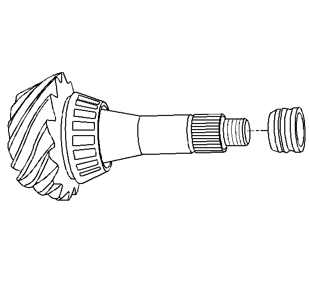
- Remove the collapsible spacer from the pinion. Discard the spacer.
- Remove the drive pinion bearing cups from the axle housing using a hammer and a brass drift in the slots provided. Move the drift back and forth between one side of the cup and the other in order to work the cups out of the housing evenly.


