Removal Procedure
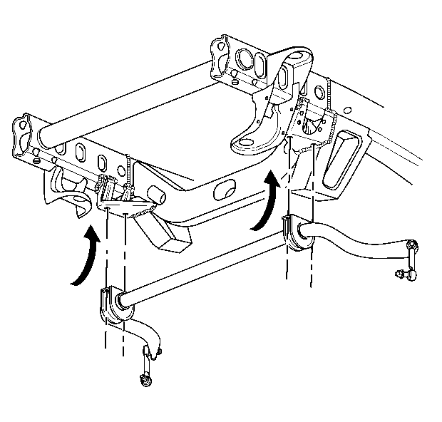
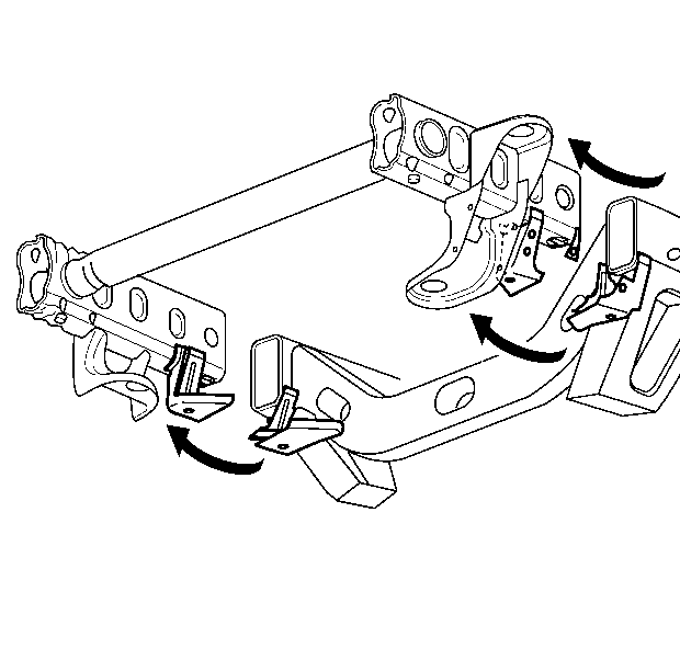
Important: Front frame service section installation requires replacement of the sway-bar mounting brackets.
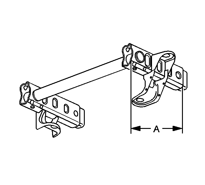
The re-designed frame assembly for the new S/T Utility is a mild, steel hydroformed frame assembly. A front frame service section consisting of the left and right frame ends, body, and radiator support mounting brackets and front connecting cross tube is available. If damage permits, locate and cut off the front 420 mm (16 ½ in) portion of the frame assembly first along the die mark indicators and through the sway bar mounting brackets. The front and rear body mounts, radiator support mounts, sway-bar brackets, steering gear and transmission cross-member can be ordered and replaced separately.
- Remove all of the related panels and components including the front bumper assembly and the sway bar brackets.
- Locate the two die-marks on each frame. The die marks are located 420 mm (16 ½ in) rearward from each front frame rail end on the top and bottom side of each rail.
- Apply masking tape over the die-marks and down each frame rail side as shown, for the cut location..
- Cut each frame at the rear edge of the tape line and through the sway bar bracket using a reciprocating saw or equivalen, as shown.
- Cut the sway bar bracket in half.
- Remove the damaged frame section.
- Remove and discard the remaining sway bar bracket attached to the undamaged portion of the frame using a cut-off wheel or equivalent.
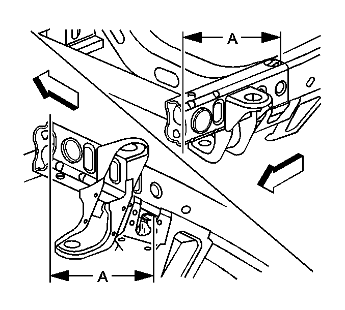
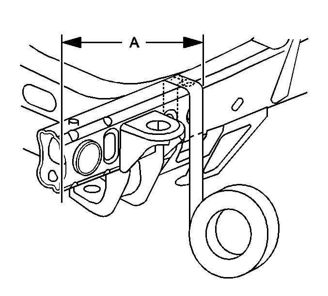
Important: Line up the masking tape with the point of each die mark arrow.
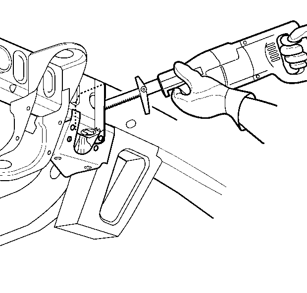
Important: The tape edge facing the rear of the vehicle is the proper cut location. The cut location is not to exceed 420 mm (16 ½ in) of the front frame section.
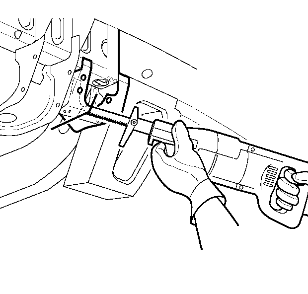
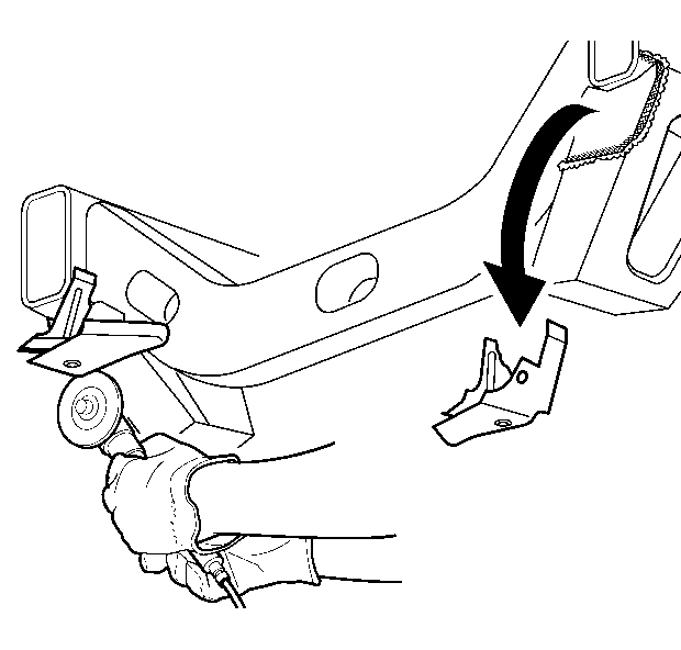
Important: Do not damage the sway bar bracket attaching the surfaces.
Installation Procedure
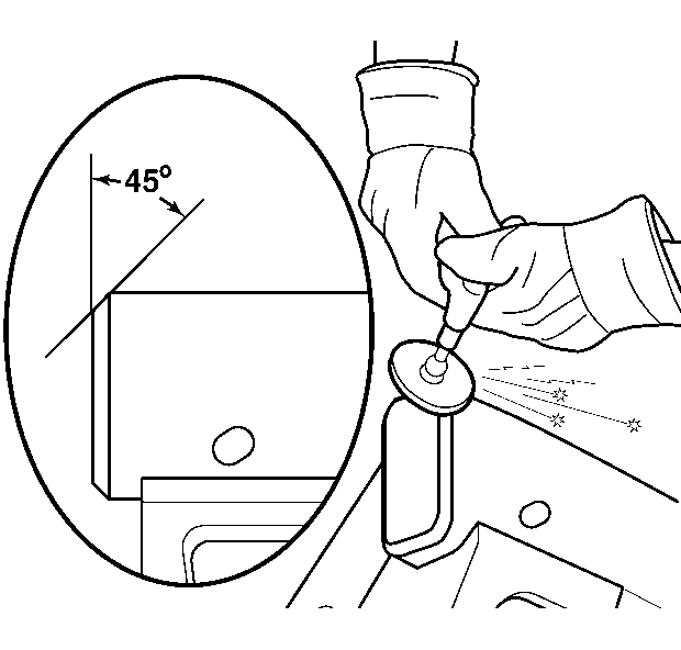
- Grind the existing frame rail seam to taper seam at a 45° angle.
- Prepare all of the attaching surfaces as necessary.
- Apply the weld-thru primer to all of the welded surfaces.
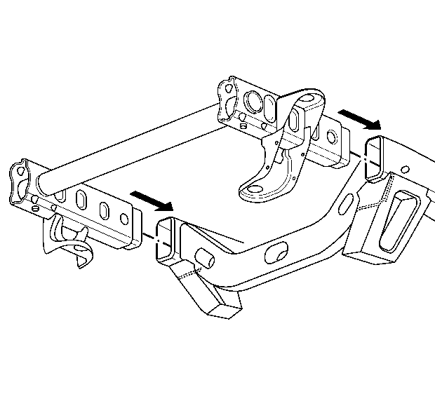
- Position the service frame section to the existing frame and clamp in place.
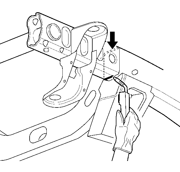
- Continuous-weld the upper and lower horizontal joints from corner to corner.
- Continuous-weld the inner and outer vertical joints from corner to corner.
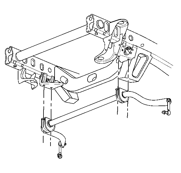
- Position the new sway bar brackets and clamp in place.
- Continuous-weld the sway bar bracket in place as noted from the original parts.
- Clean and prepare all of the welded surfaces.
- Install all of the related panels and components.
Important: Verify the frame measurements three-dimensionally to ensure proper position of the service frame.
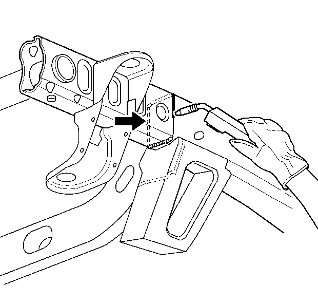
Important: Verify the frame measurements three-dimensionally to ensure proper position of the service frame.
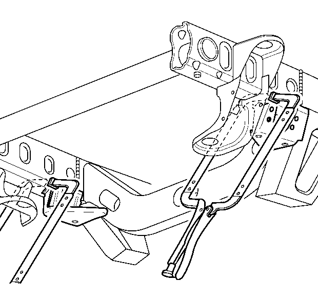
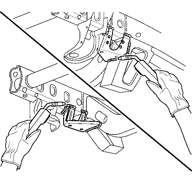
Important: Verify the frame measurements three-dimensionally to ensure proper position of the sway bar brackets.
