SMU - Revised Stabilizer Shaft Replacement

| Subject: | Revised Stabilizer Shaft Replacement |
| Models: | 2004-2005 Buick Rainier |
| 2004-2005 Chevrolet SSR, TrailBlazer Models |
| 2004-2005 GMC Envoy Models |
| 2004 Oldsmobile Bravada |
| 2005 Saab 9-7X |
This bulletin is being issued to revise the Stabilizer Shaft Replacement procedure in the Front Suspension sub-section of the Service Manual. Please replace the current information in the Service Manual with the following information.
The following information has been updated within SI. If you are using a paper version of this Service Manual, please make a reference to this bulletin on the affected page.
Stabilizer Shaft Replacement (TrailBlazers, Envoys, Rainier, Bravada, 9-7X)
Removal Procedure
- Raise and support the vehicle. Refer to Lifting and Jacking the Vehicle in General Information.
- Remove the tires and wheels. Refer to Tire and Wheel Removal and Installation in Tires and Wheels.
- Remove the stabilizer shaft links to the stabilizer shaft retaining nuts. Refer to Stabilizer Shaft Link Replacement.
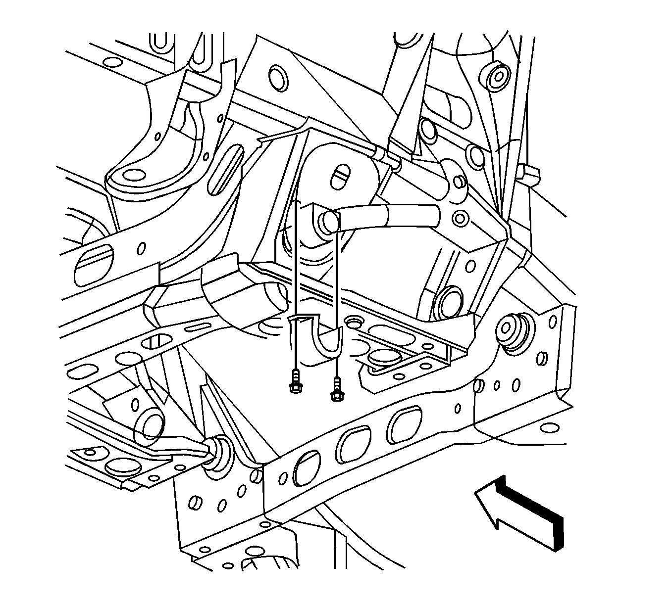
- Remove the stabilizer shaft insulator clamp mounting bolts.
- Remove the stabilizer shaft insulator clamp from the stabilizer shaft insulator.
- Remove the stabilizer shaft insulators from the stabilizer shaft.
- Remove the engine protection shield. Refer to Engine Protection Shield Replacement in Frame and Underbody.
- Install a pole jack underneath the oil pan.
- Insert a block of wood between the oil pan and the pole jack.
- Raise the engine 10 mm measuring from the bottom of the oil pan to the rear edge of the transmission support crossmember.
- Remove the stabilizer shaft from the vehicle.

Important: Note the position of the bend in the stabilizer shaft.

Important: The jackstand should only be used to support the weight of the powertrain. DO NOT lift the entire weight of the front end of the vehicle by the jackstand.
Installation Procedure
- Install the stabilizer shaft to the vehicle, with the bend down and away from the engine. There may be a label on the shaft. If so, it should be on the LH side.
- Lower the engine.
- Remove the block of wood between the oil pan and the pole jack.
- Remove the jackstand from underneath the oil pan.
- Install the engine protection shield. Refer to Engine Protection Shield Replacement in Frame and Underbody.
- Install the stabilizer shaft insulators to the stabilizer shaft.
- Install the stabilizer shaft insulator clamp to the stabilizer shaft insulator.
- Install the stabilizer shaft insulator clamp mounting bolts.
- Install the stabilizer shaft links to the stabilizer shaft. Refer to Stabilizer Shaft Link Replacement.
- Install the tires and wheels. Refer to Tire and Wheel Removal and Installation in Tires and Wheels.
- Lower the vehicle.

Notice: The stabilizer shaft must be installed with the bend down and away from the engine. If the stabilizer shaft is installed improperly, contact between the stabilizer shaft and oil filter may occur.

Notice: Refer to Fastener Notice in Cautions and Notices.
Tighten
Tighten the stabilizer shaft insulator clamp mounting bolts to 55 N·m (41 lb ft).
Stabilizer Shaft Replacement (SSR)
Removal Procedure
- Raise and support the vehicle. Refer to Lifting and Jacking the Vehicle in General Information.
- Remove the tires and wheels. Refer to Tire and Wheel Removal and Installation in Tires and Wheels.
- Remove the stabilizer shaft links to the stabilizer shaft retaining nuts. Refer to Stabilizer Shaft Link Replacement.
- Remove the stabilizer shaft insulator clamp mounting bolts.
- Remove the stabilizer shaft insulator clamp from the stabilizer shaft insulator.
- Remove the stabilizer shaft insulators from the stabilizer shaft.
- Install a pole jack underneath the oil pan.
- Insert a block of wood between the oil pan and the pole jack.
- Raise the engine 10 mm measuring from the bottom of the oil pan to the rear edge of the transmission support crossmember.
- Remove the stabilizer shaft from the vehicle.

Important: Note the position of the bend in the stabilizer shaft.

Important: The jackstand should only be used to support the weight of the powertrain. DO NOT lift the entire weight of the front end of the vehicle by the jackstand.
Installation Procedure
- Install the stabilizer shaft to the vehicle, with the bend down and away from the engine. There may be a label on the shaft. If so, it should be on the LH side.
- Lower the engine.
- Remove the block of wood between the oil pan and the pole jack.
- Remove the jackstand from underneath the oil pan.
- Install the stabilizer shaft insulators to the stabilizer shaft.
- Install the stabilizer shaft insulator clamp to the stabilizer shaft insulator.
- Install the stabilizer shaft insulator clamp mounting bolts.
- Install the stabilizer shaft links to the stabilizer shaft. Refer to Stabilizer Shaft Link Replacement.
- Install the tires and wheels. Refer to Tire and Wheel Removal and Installation in Tires and Wheels.
- Lower the vehicle.

Notice: The stabilizer shaft must be installed with the bend down and away from the engine. If the stabilizer shaft is installed improperly, contact between the stabilizer shaft and oil filter may occur.

Notice: Refer to Fastener Notice in Cautions and Notices.
Tighten
Tighten the stabilizer shaft insulator clamp mounting bolts to 55 N·m (41 lb ft).
