For 1990-2009 cars only
Removal Procedure
- Remove the brake modulator assembly. Refer to Brake Pressure Modulator Valve Assembly Replacement .
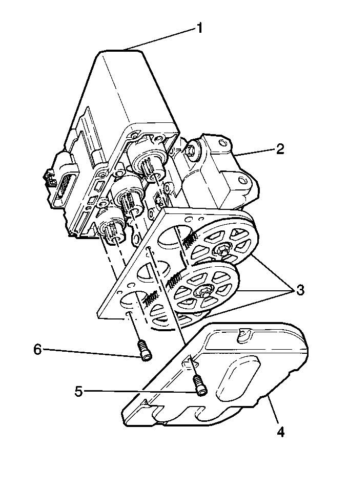
- Remove the Torx® head screws (5) attaching the gear cover (4).
- Remove the gear cover (4).
- Remove the four Torx® head screws (6) attaching the motor pack (1) to the brake modulator (2).
- Remove the motor pack (1) from the brake modulator (2).
- Remove the Torx® head screws that retain the proportioning valve.
- Remove the proportioning valve.

Installation Procedure
Important: When replacing the ABS brake modulator, install the three gears in the same location on the replacement brake modulator. Refer to Brake Modulator Gear Replacement .
No repair of the ABS brake modulator is authorized. Replace the ABS brake modulator as an assembly.- Install the proportioning valve to the hydraulic modulator.
- Install the Torx® head screws that retain the proportioning valve to the hydraulic modulator.
- With the ABS brake modulator positioned upside down, and the gears facing you, rotate each ABS brake modulator gear clockwise until movement stops.
- Install the ABS brake motor pack (1) onto the brake modulator assembly (2).
- Install the four Torx® head screws (6) that retain the motor pack (1) to the brake modulator (2).
- Install the gear cover (4) to the brake modulator assembly (2).
- Install the Torx® head screws (5) that retain the gear cover (4).
- Install the brake modulator assembly. Refer to Brake Pressure Modulator Valve Assembly Replacement .
- Perform the Diagnostic System Check.

Tighten
Tighten the Torx® head screws to 12 N·m (106 lb. in.).
Important: A new gasket MUST be used when installing the Proportioning Valve.
The procedure causes the following conditions:
| • | The pistons are positioned very close to the top of the modulator bore. |
| • | The brake bleeding procedure is simplified. |
Tighten
Tighten the four Torx® head screws to 5 N·m (44 lb in).
Tighten
Tighten the Torx® head screws to 4 N·m (36 lb in).
