ELIMINATE SQUEAK AND RATTLE NOISE IN INSTRUMENT PANEL

VEHICLES AFFECTED: 1988-89 OLDSMOBILE CUTLASS
Elimination of squeak and rattle noise from the instrument panel (I/P) area may be accomplished with the use of the following procedure:
VIN Breakpoints
All 1988 and 1989 Cutlass built prior to KD343202 require both upper and lower braces.
All 1989 Cutlass built after D343202 and before D358417 require upper brace, P/N 10143726 only.
Parts Required:
10143728 I/P Lower Bracket 11509709 Bolt / Screw
Additional Parts Required:
- 3M (R) Foam Tape # 06370 or equivalent Adhevise backed black felt (local fabric store) Procedure:
1. Remove: (See Service Manual Section 8C)
A). Defroster outlet grill. B). Glove box and glove box light switch. C). Cluster trim plate bezel. D). Instrument panel pad. E). Radio and speakers. F). Lower hush panel - passenger side. G). Three (3) upper right carrier attaching bolts. H). One lower right carrier attaching bolt.
Right hand side of carrier should now be loose. Carefully pull carrier slightly outward.
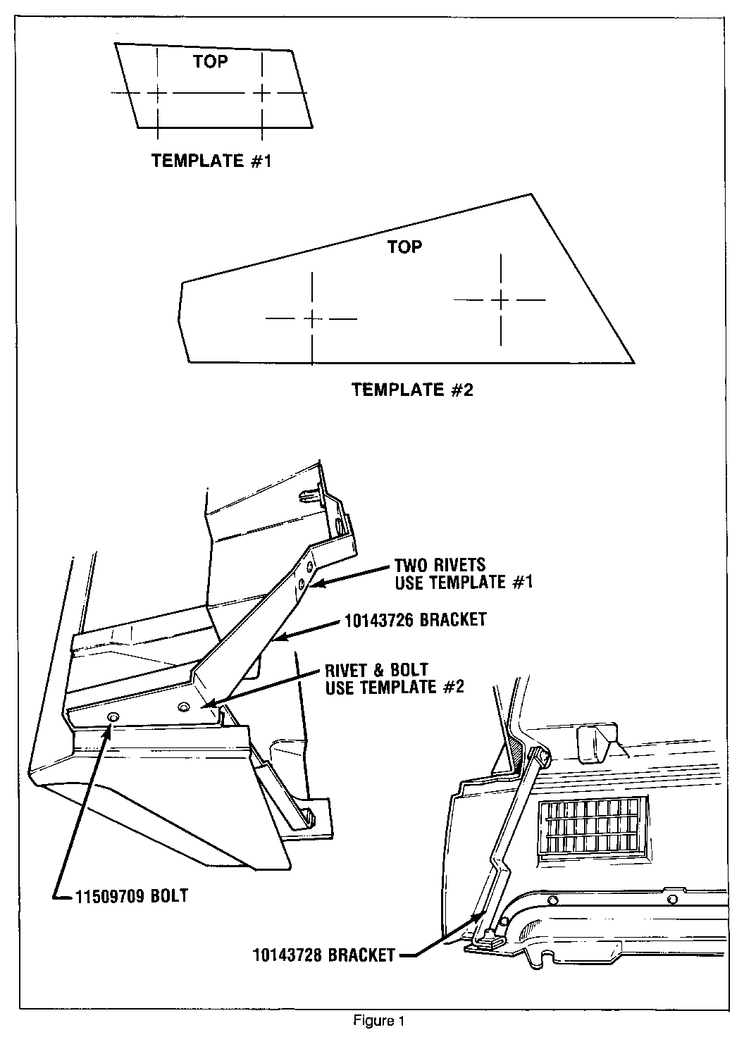
2. Align I/P bracket P/N 10143726, behind and along right outer side of carrier, the large predrilled hole at top of bracket must align with first upper mounting hole in the carrier. Note location of predrilled holes in bracket to be used for rivet and bolt attachments.
3. Using templet #1 mark location for drilling two 1/16 inch holes at top right of carrier (See Illustration).
4. Using templet #2 mark location for drilling two 1/8 inch holes at lower edge of carrier (See Illustration). Also, use templet to mark location of hole to be drilled in bracket lower side.
5. Drill all holes at previously marked locations, and attach bracket with one rivet at top of carrier.
6. Bracket P/N 10143728 is to be installed on the extreme right under side of the carrier.
7. Remove and discard J-nut on lower carrier attachment.
8. Align lower bracket between hole drilled in side of carrier (Step 4) and lower carrier attachment, and bolt in place.
9. Install two remaining rivets and tighten bolts. Move carrier assembly into place and reinstall attaching bolts.
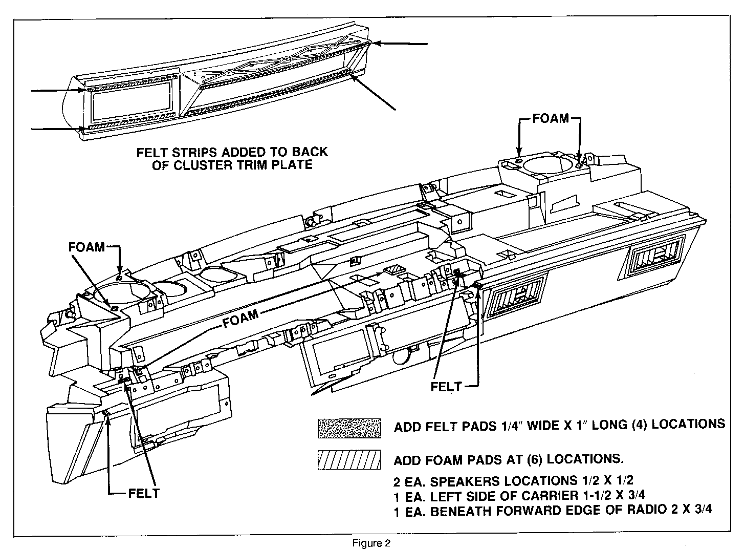
10. Add adhesive back felt strips to back of cluster bezel and front of carrier as shown on attached Illustration (4 locations).
11. Remove radio speakers and apply 3M (R) Foam Rubber #06370 cut in 1/2 inch squares opposite attachments. See Illustration.
12. Apply 2 inch strip of foam tape to carrier beneath forward edge of radio, and a 1 1/2 inch strip at left side of carrier as indicated on Illustration.
13. Reinstall all previously removed parts.
14. Check glove box door for rattle by taping lightly on door in closed position. If rattle is present, add strips of foam as required to eliminate rattle condition.
Use most applicable Labour operation from the Canadian Labour Time Guide
Labour Time ...........1.3 Hours


General Motors bulletins are intended for use by professional technicians, not a "do-it-yourselfer". They are written to inform those technicians of conditions that may occur on some vehicles, or to provide information that could assist in the proper service of a vehicle. Properly trained technicians have the equipment, tools, safety instructions and know-how to do a job properly and safely. If a condition is described, do not assume that the bulletin applies to your vehicle, or that your vehicle will have that condition. See a General Motors dealer servicing your brand of General Motors vehicle for information on whether your vehicle may benefit from the information.
