Tools Required
| • | J 25025 Guide Pins |
| • | J 36850 Assembly Lubricant |
- Inspect the spacer plate (370) from the control valve body for the following:
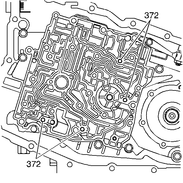
- Inspect each check valve seat (370) for excessive peening. Place a ball check valve (372) on each seat and use a flashlight in order to look for visible light between the valve and the seat.
- Place the ball check valves (372) into the valve seats in the case cover.
- Use J 36850 or equivalent in order to hold the valves in position.
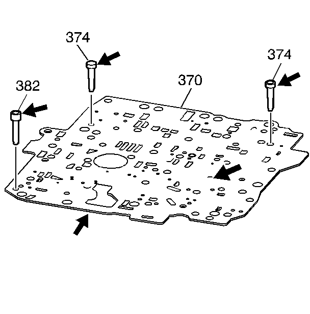
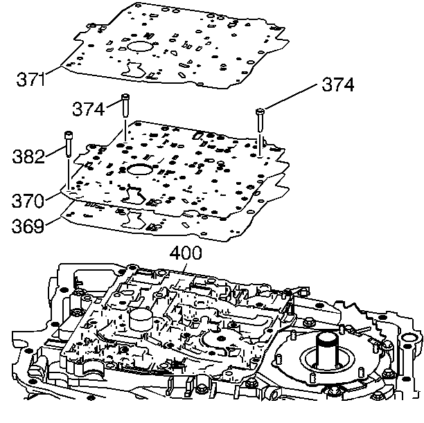
- Insert the solenoid screens (374) into the valve body spacer plate (370).
- Insert the TCC orifice screen (382) into the valve body spacer plate (370).
- Assemble the valve body spacer plate and two spacer plate gaskets (369, 371) onto the channel plate (400).
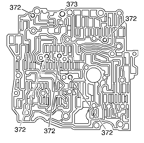
- Position the check ball valves (372, 373) onto the valve body assembly. Retain the valves with J 36850 or equivalent.
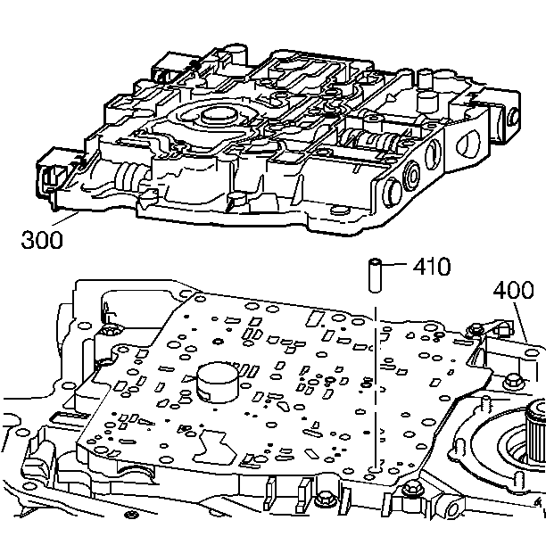
- Install the control valve body alignment sleeve (410) into the case cover (400).
- Install the control valve assembly (300) onto the case cover and the guide pins (410).
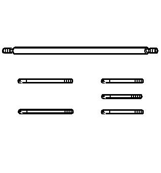
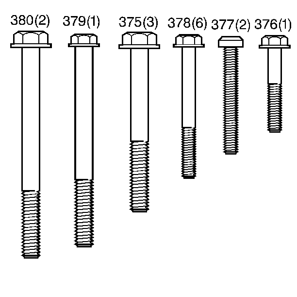
- Install the retaining bolts (375-380) into the valve body at the locations indicated.
- Tighten the valve body assembly bolts.
| • | Bent or stuck thermal elements |
| • | Plugged holes |
| • | Damage from being bent |
| • | Plugged or damaged solenoid screens |
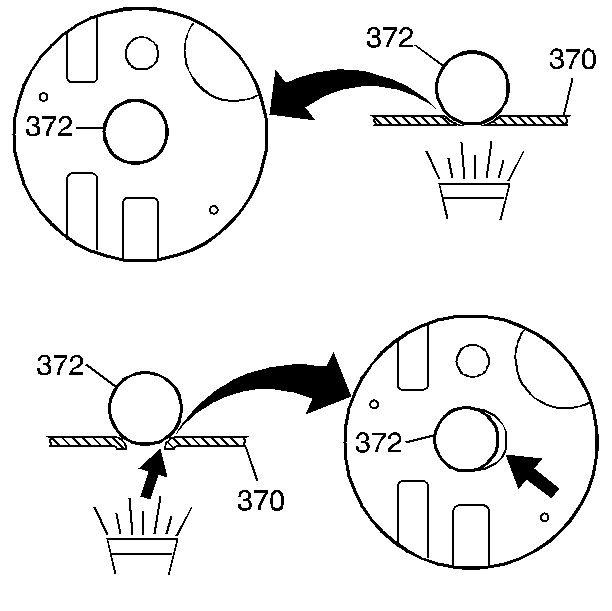
Important: Be sure that the check ball valves do not fall out of the valve body assembly during installation.
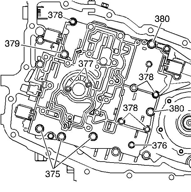
Important: Tighten and torque the bolts in a spiral pattern starting from the center. If the bolts are torqued at random, valve bores may become distorted and inhibit proper valve operation.
Notice: Use the correct fastener in the correct location. Replacement fasteners must be the correct part number for that application. Fasteners requiring replacement or fasteners requiring the use of thread locking compound or sealant are identified in the service procedure. Do not use paints, lubricants, or corrosion inhibitors on fasteners or fastener joint surfaces unless specified. These coatings affect fastener torque and joint clamping force and may damage the fastener. Use the correct tightening sequence and specifications when installing fasteners in order to avoid damage to parts and systems.
Tighten
| • | Tighten bolts 380, 379, 375 to 25 N·m (18 lb ft). |
| • | Tighten bolts 376, 378 to 12 N·m (106 lb in). |
| • | Tighten bolts 377 to 12 N·m (106 lb in). |
