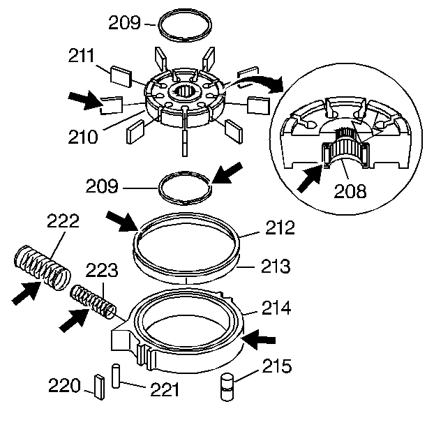
- Inspect the oil pump for the following:
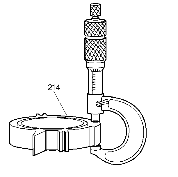
| • | A worn, scored, or gouged pump slide (214) |
| • | Cracks, wear, or damage to the rotor (210), or the vanes (211) |
| • | Cuts or damage to the seals (212, 213) |
| • | Broken priming springs (222, 223) |
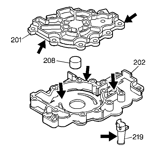
- Inspect the oil pump body (202) for the following:
| • | A worn, scored, or damaged pump pocket |
| • | Interconnected oil passages |
| • | Damaged machine surfaces |
- Inspect the pressure screen assembly (219) for damage or debris.
- Inspect the oil pump cover (201) for cracks, wear, or gouges from
the pump vanes.
- Inspect the bushing (208) for wear, scoring, and scratches.
Important: Laser marks on the oil pump body indicate the size of the selective
parts which were used in assembly. If these correct parts are not selected
for replacement, damage to the oil pump and to the transmission will occur.
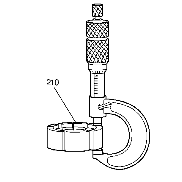
- Measure the pump rotor (210).
- Select the proper replacement size. Refer to the Rotor Selection
table found in
Oil Pump Specifications
.
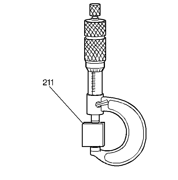
- Measure the oil pump vanes (211).
- Select the proper replacement size. Refer to the Vane Selection
table found in
Oil Pump Specifications
.
- Measure the oil pump slide (214).
- Select the proper replacement size. Refer to the Slide Selection
table found in
Oil Pump Specifications
.
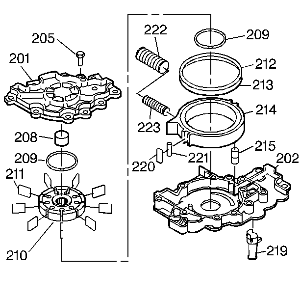
- Insert the oil pump screen (219).
- Insert the pump slide seal (221) and the support (220) into the
slot on the slide (214).
- Insert the pump slide (214) and the pivot pin (215) into the pump
body (202).
- Install the inner and the outer priming springs (222, 223) as
an assembly into the pump body (202).
- Install the first vane ring (209).
- Insert the oil seal (213) and the oil seal ring (212) into the
slide.
- Insert the rotor (210) into the pump body (202).
- Assemble the pump vanes (211) into the rotor (210). The vanes
must be flush with the top of the rotor.
- Install the second vane ring (209).
Notice: Use the correct fastener in the correct location. Replacement fasteners
must be the correct part number for that application. Fasteners requiring
replacement or fasteners requiring the use of thread locking compound or sealant
are identified in the service procedure. Do not use paints, lubricants, or
corrosion inhibitors on fasteners or fastener joint surfaces unless specified.
These coatings affect fastener torque and joint clamping force and may damage
the fastener. Use the correct tightening sequence and specifications when
installing fasteners in order to avoid damage to parts and systems.
- Insert the pump
cover (201) and the bolt (205).
Tighten
Tighten the bolts to 25 N·m (18 lb ft).
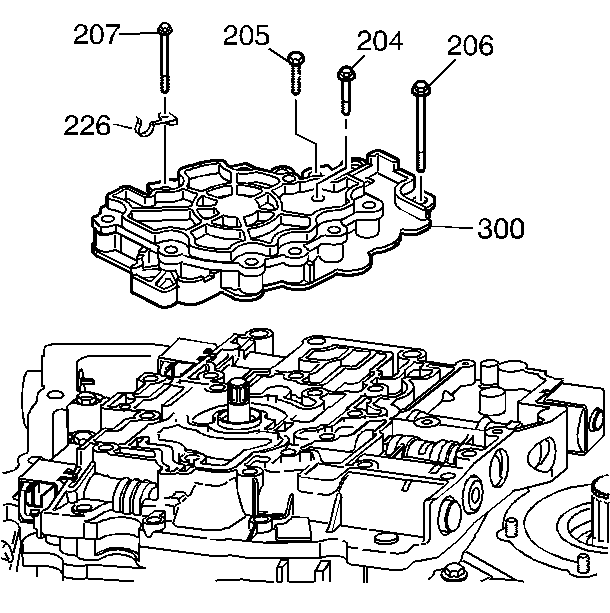
- Install the transmission
oil pump assembly (300) onto the control valve assembly.
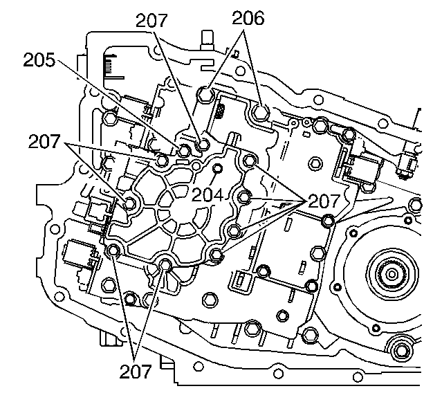
- Install the 11 oil pump
bolts as indicated (204, 206, 207)
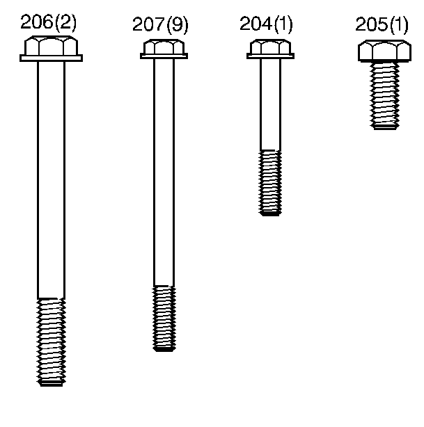
- Tighten the bolts (204, 205,
206, 207).
Tighten
| • | Tighten the bolts (204, 207) to 12 N·m (106 lb in). |
| • | Tighten the bolts (205) to 25 N·m (18 lb ft). |
| • | Tighten the bolts (206) to 33 N·m (24 lb ft). |
