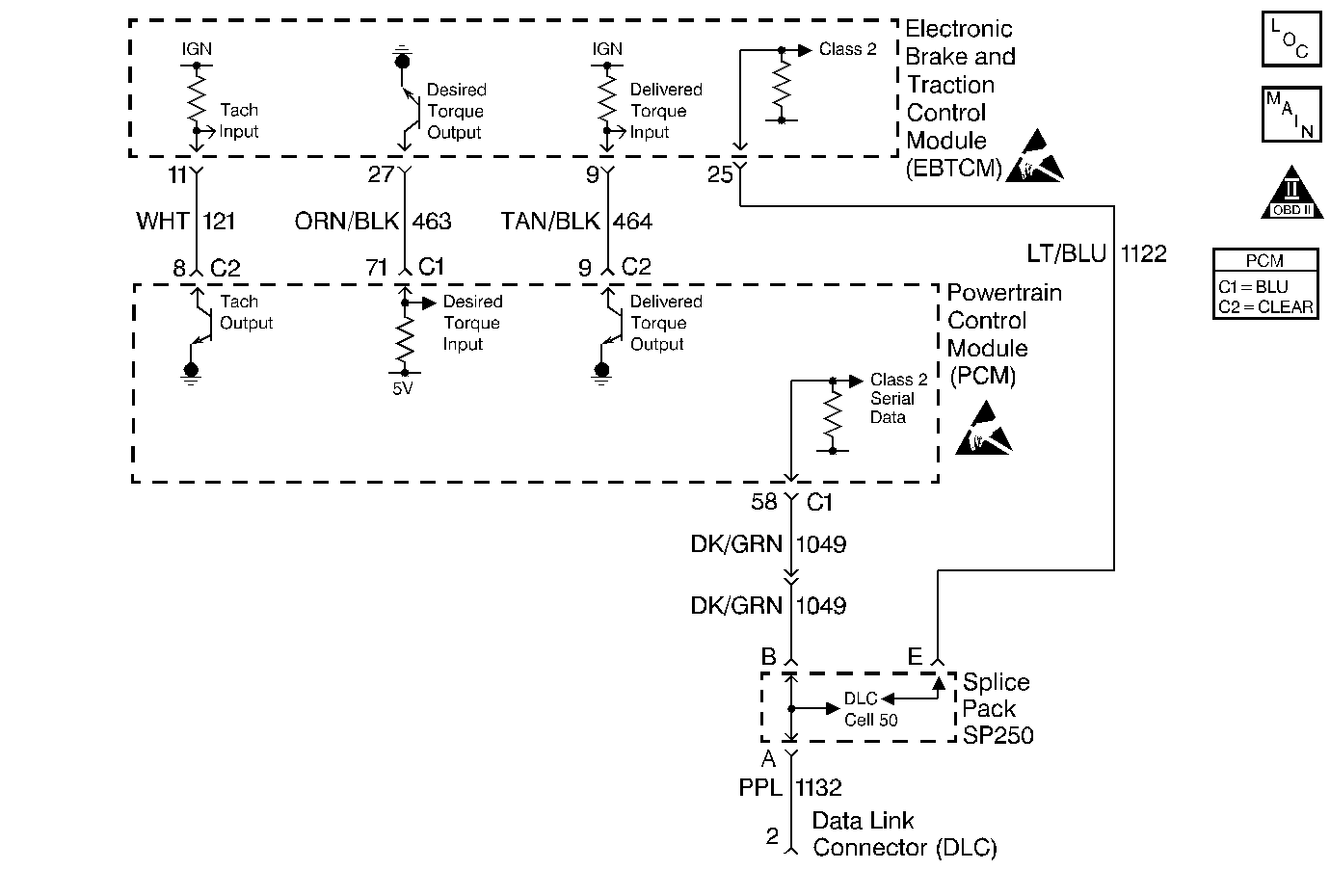
Circuit Description
The EBTCM pulls the Traction Control Delivered Torque circuit up to approximately 12 volts. The PCM Pulse Width Modulates (PWM) the circuit to ground creating a signal that represents the percentage of engine torque output. The EBTCM uses this PWM signal for traction control. The PCM provides the ground via an internal solid state device called a driver. The primary function of the driver is to supply the ground for the component being controlled. Each driver has a fault line which is monitored by the PCM. If the fault detection circuit senses a voltage other than what is expected, this DTC will set.
Conditions for Running the DTC
| • | Brakes not applied. |
| • | PCM in Closed Loop fuel control. |
Conditions for Setting the DTC
The PCM detects an incorrect voltage on the Traction Control Delivered Torque circuit.
Condition present for 2.5 seconds.
Action Taken When the DTC Sets
| • | The powertrain control module (PCM) stores the DTC information into memory when the diagnostic runs and fails. |
| • | The malfunction indicator lamp (MIL) will not illuminate. |
| • | The PCM records the operating conditions at the time the diagnostic fails. The PCM stores this information in the Failure Records. |
Conditions for Clearing the MIL/DTC
| • | A History DTC will clear after forty consecutive warm-up cycles, if no failures are reported by this or any other non-emission related diagnostic. |
| • | A last test failed (Current DTC) will clear when the diagnostic runs and does not fail. |
| • | Use a scan tool in order to clear the MIL/DTC. |
| • | Interrupting the PCM battery voltage may or may not clear DTCs. This practice is not recommended. Refer to Powertrain Control Module Description , Clearing Diagnostic Trouble Codes. |
Diagnostic Aids
Notice: Use the connector test adapter kit J 35616-A for any test that
requires probing the following items:
• The PCM harness connectors • The electrical center fuse/relay cavities • The component terminals • The component harness connector
Check for an intermittent poor connection at both the PCM and the EBTCM.
If the problem is intermittent, refer to Intermittent Conditions .
Test Description
Number(s) below refer to the step number(s) on the Diagnostic Table.
Step | Action | Value(s) | Yes | No | ||||||
|---|---|---|---|---|---|---|---|---|---|---|
1 | Did you perform the Powertrain On-Board Diagnostic (OBD) System Check? | -- | ||||||||
2 |
Does the display indicate OK continuously? | -- | Refer to Diagnostic Aids. | |||||||
3 |
Is the voltage the same or more than the value specified? | 10.0 volts | ||||||||
4 |
Was a problem found and corrected? | 5 ohms | ||||||||
5 | Check for poor connections/terminal tension at the PCM. Refer to Intermittents and Poor Connections Diagnosis . Was a problem found and corrected? | -- | ||||||||
6 | Check for poor connections/terminal tension at the EBTCM. Refer to Intermittents and Poor Connections Diagnosis . Was a problem found and corrected? | -- | Go to Diagnostic System Check - ABS in Antilock Brake System Delco VI or Diagnostic System Check - ABS in Antilock Brake System Bosch 5.3 | |||||||
7 | Replace the PCM. Important:: The replacement PCM must be programmed. Refer to Powertrain Control Module Replacement/Programming Is the action complete? | -- | -- | |||||||
8 |
Does the scan tool indicate that this test ran and passed? | -- | ||||||||
9 | Review Captured Info using the scan tool. Are there any DTCs that have not been diagnosed? | -- | Go to the applicable DTC table | System OK |
