For 1990-2009 cars only
Camshaft Removal Left
Tools Required
J 42038 Camshaft Holding Fixture
- Remove the J 42038 from the left cylinder head camshafts. Allow the camshaft lobes to find a neutral position by rotating each camshaft, if necessary.
- Observe the markings on the bearing caps. Each bearing cap is marked in order to identify its location. The markings have the following meanings:
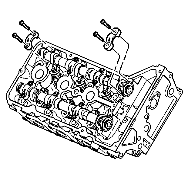
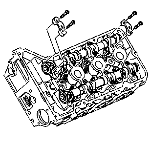
- Remove the camshaft bearing cap bolts.
- Remove the camshaft bearing caps. The cap closest to the front of the engine is the thrust cap and must not be installed in another location.
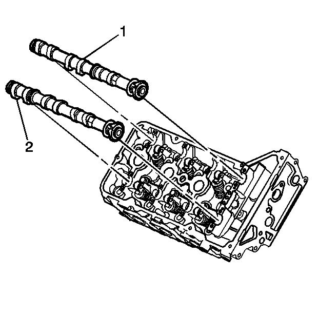
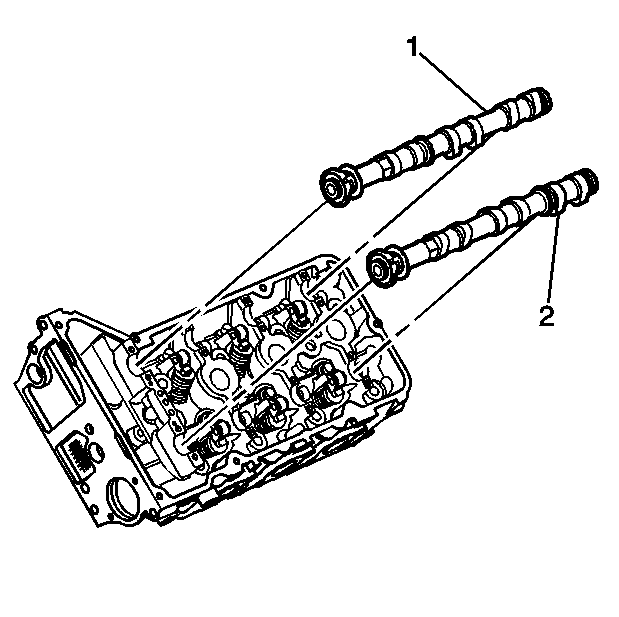
- Lift the camshaft (1 and 2) out of the cylinder head.
- Cover the camshaft with an oil soaked towel in order to prevent corrosion.
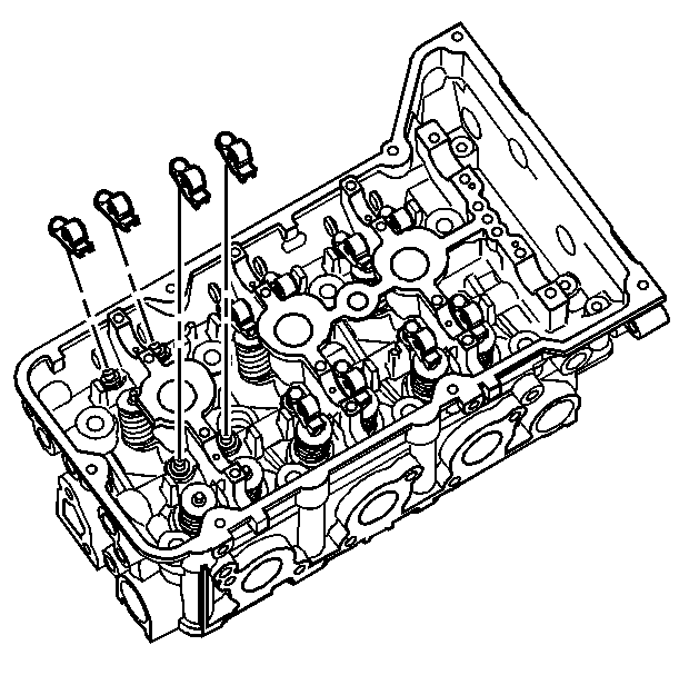
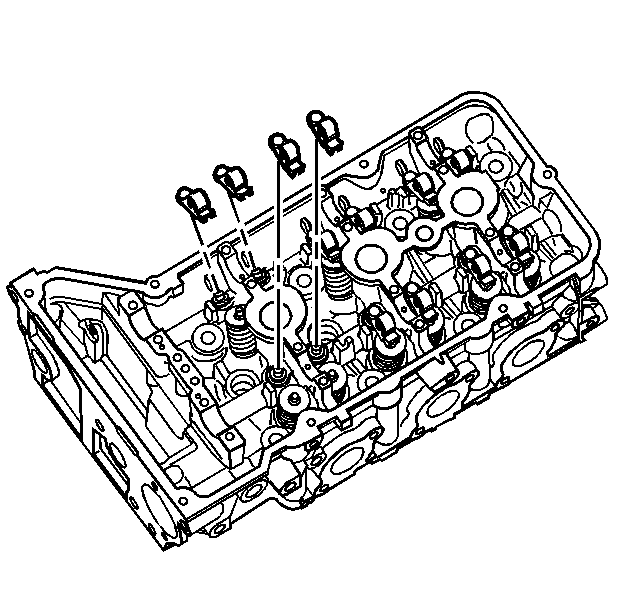
- Remove the camshaft followers from the cylinder head. Keep the followers in the order they were removed.
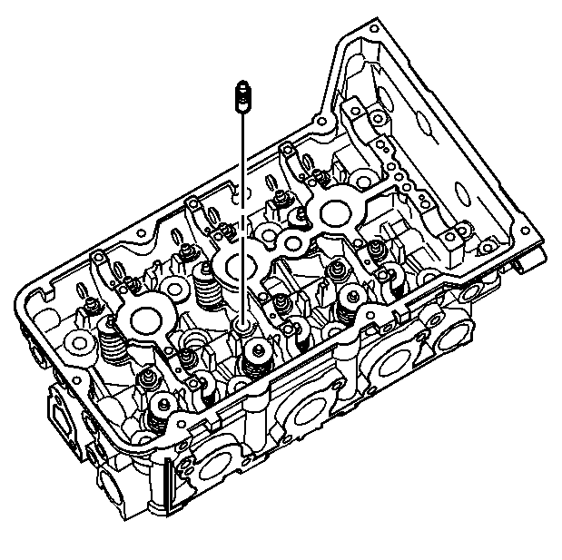
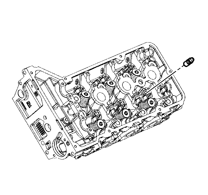
- Remove the stationary hydraulic lash adjusters (SHLA) from the cylinder head bores. Keep the SHLAs in the order they were removed.
- Store the camshafts, followers and SHLAs in a clean, secure location.
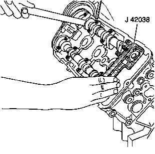
Important: DO NOT rotate the camshafts more than 10 degrees.
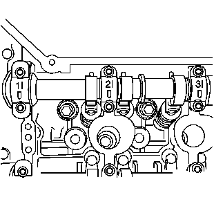
| • | The raised feature must always be oriented toward the outboard side of the engine. |
| • | The I indicates the intake camshaft. |
| • | The E indicates the exhaust camshaft. |
| • | The number indicates the journal position from the front of the engine. |
Camshaft Removal Right
Tools Required
J 42038 Camshaft Holding Fixture
- Remove the J 42038 from the right cylinder head camshafts. Allow the camshaft lobes to find a neutral position by rotating each camshaft, if necessary.
- Observe the markings on the bearing caps. Each bearing cap is marked in order to identify its location. The markings have the following meanings:
- Remove the camshaft bearing cap bolts.
- Remove the camshaft bearing caps. The cap closest to the front of the engine is the thrust cap and must not be installed in another location.
- Lift the camshaft (1 and 2) out of the cylinder head.
- Cover the camshaft with an oil soaked towel in order to prevent corrosion.
- Remove the camshaft followers from the cylinder head. Keep the followers in the order they were removed.
- Remove the stationary hydraulic lash adjusters (SHLA) from the cylinder head bores. Keep the SHLAs in the order they were removed.
- Store the camshafts, followers and SHLAs in a clean, secure location.
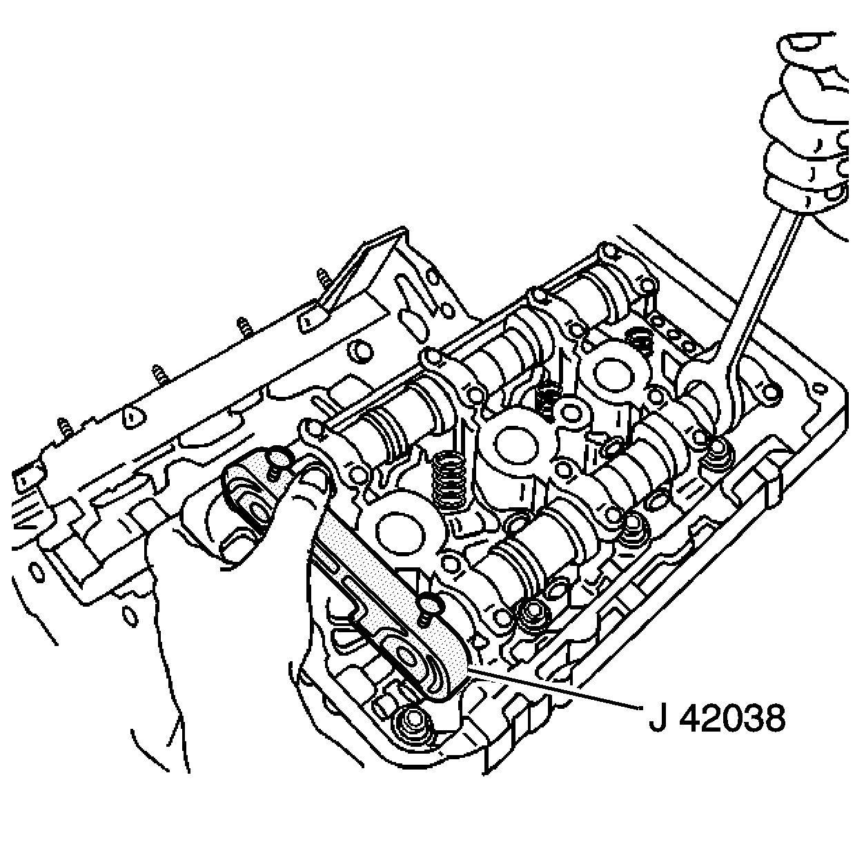
Important: DO NOT rotate the camshafts more than 10 degrees.
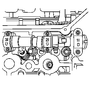
| • | The raised feature must always be oriented toward the outboard side of the engine. |
| • | The I indicates the intake camshaft. |
| • | The E indicates the exhaust camshaft. |
| • | The number indicates the journal position from the front of the engine. |
