Cylinder Head Installation Left
Tools Required
| • | J 36660-A Torque Angle Meter |
| • | J 43032 Crankshaft Rotation Socket |
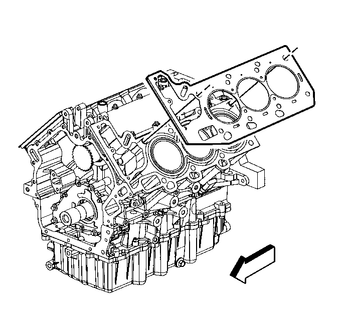
- Ensure the cylinder head locating pins are securely mounted in the cylinder block deck face.
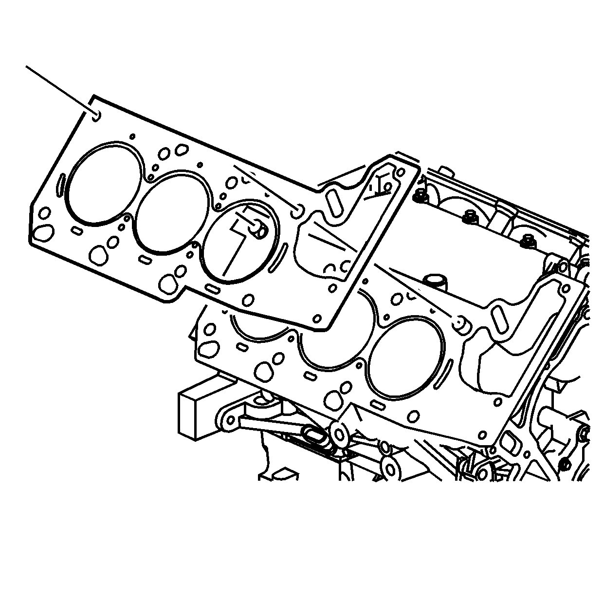
- Install a new left cylinder head gasket using the deck face locating pins for retention.
- Align the left cylinder head with the deck face locating pins.
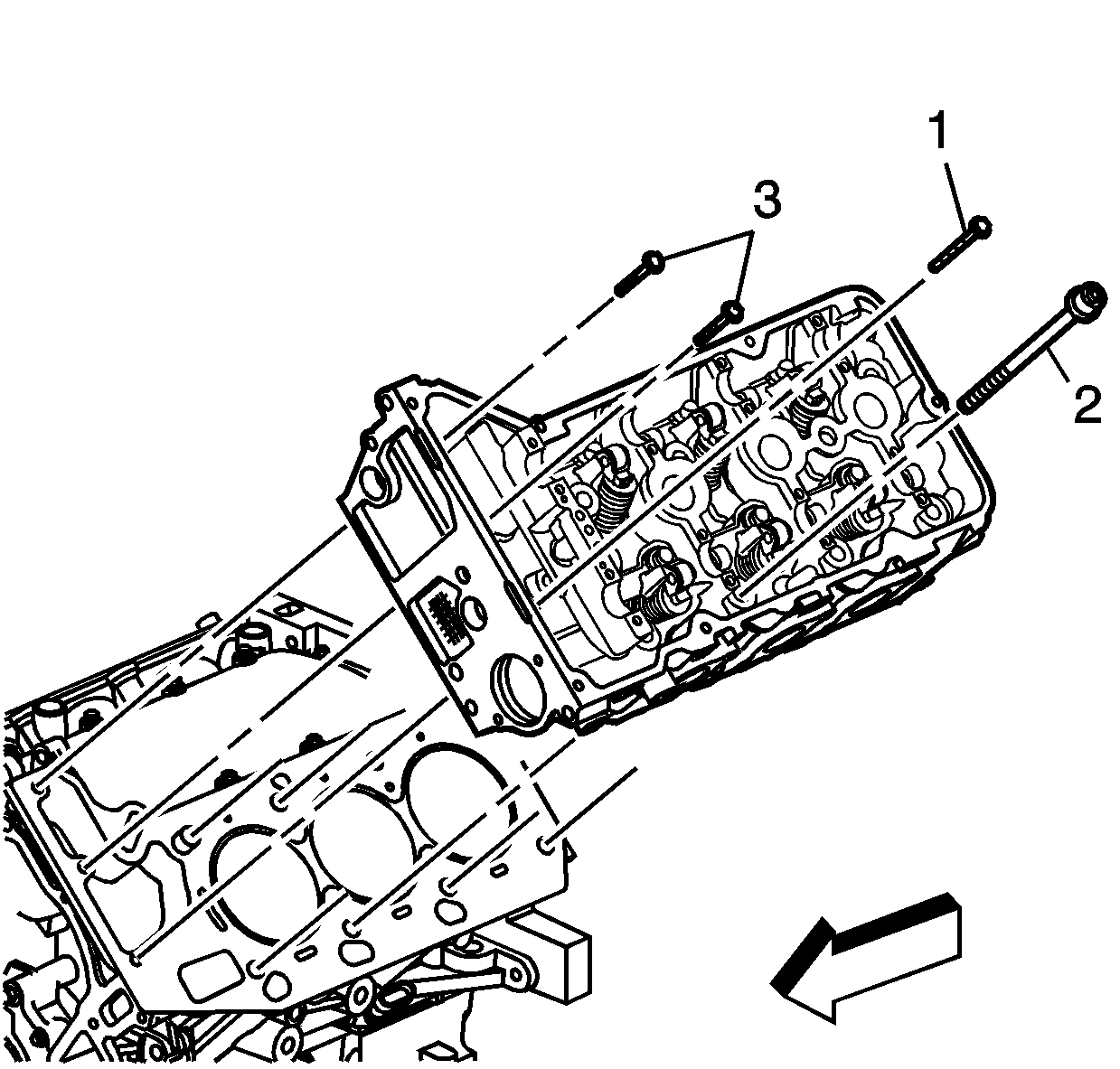
- Place the left cylinder head in position on the deck face.
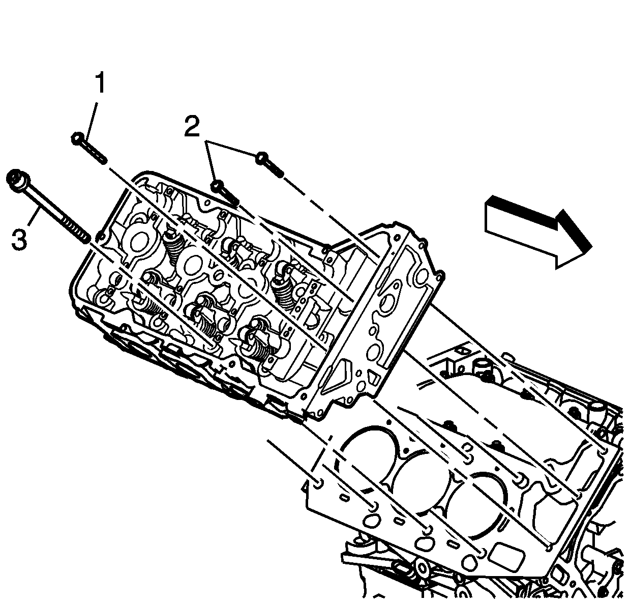
- Install new M11 cylinder head bolts (2).
- Install the M6 cylinder head bolts at the front of the left cylinder head. Install the longer M6 cylinder head bolt (1) in the outboard location as shown. Install the two shorter M6 cylinder head bolt (3) in the locations shown.
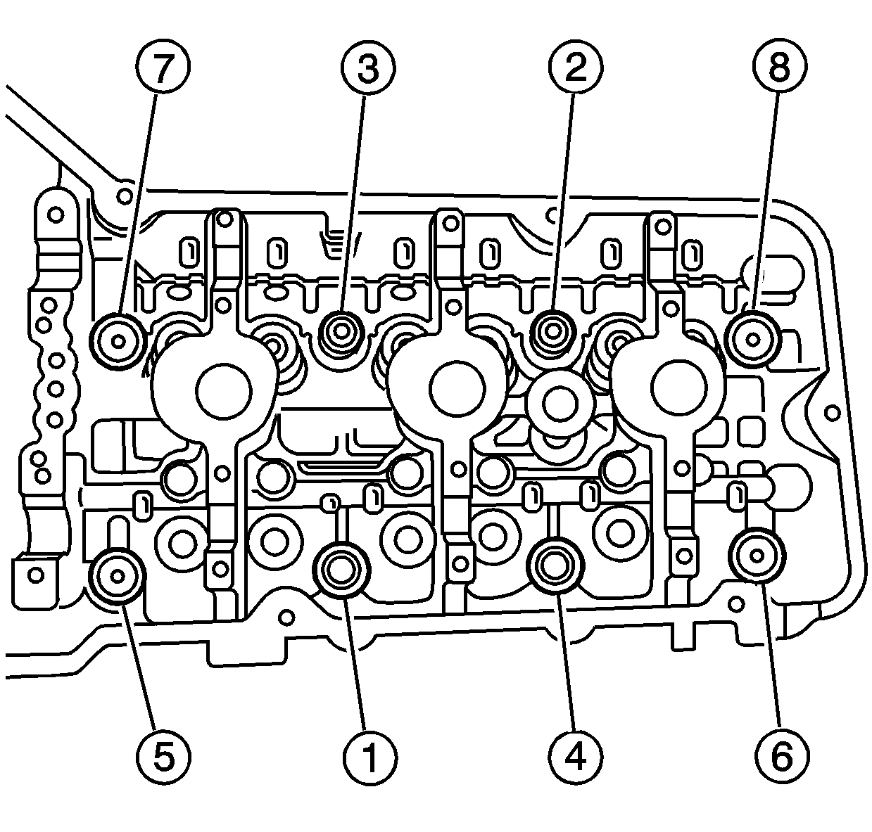
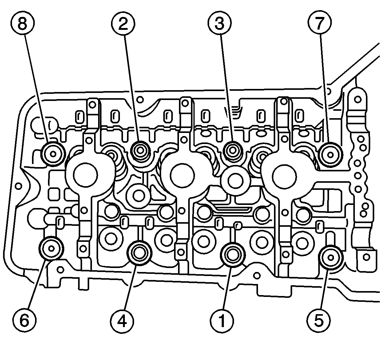
- Tighten the M11 cylinder head bolts.
- Tighten the M11 cylinder head bolts a first pass in sequence to 40 N·m (30 lb ft).
- Tighten the M11 cylinder head bolts a second pass in sequence an additional 100 degrees using the J 36660-A .
- Tighten the M11 cylinder head bolts a final pass in sequence an additional 100 degrees (200 degrees total) using the J 36660-A .
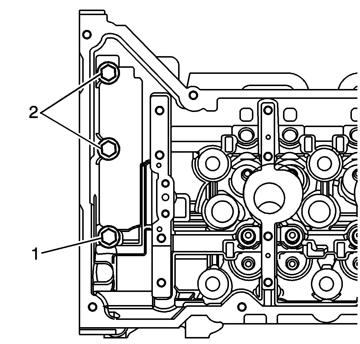
- Tighten the long M6 cylinder head bolt (1).
- Tighten the two shorter M6 cylinder head bolts (2).
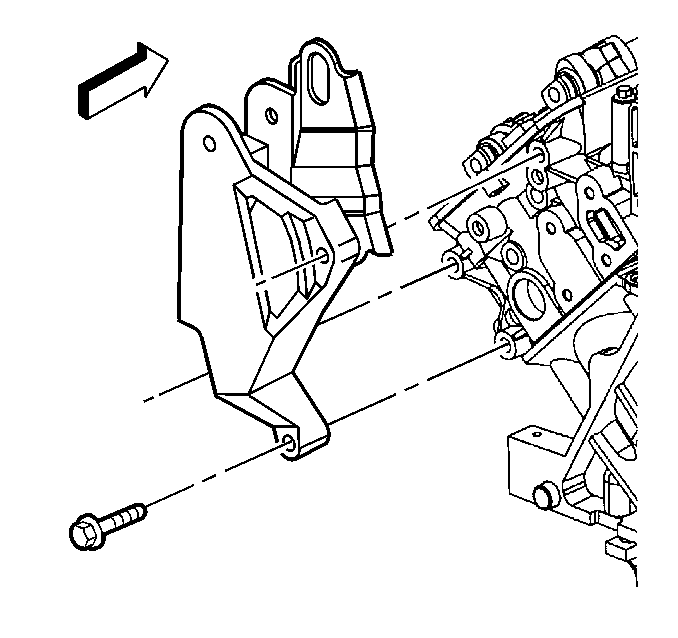
- Place the rear torque strut bracket in position on the left cylinder head.
- Install the rear torque strut bracket bolts.
Important: Ensure that the crankshaft is in the TDC position for cylinder number one using the J 43032 .
Important: DO NOT reuse the old M11 cylinder head bolts.
Notice: Use the correct fastener in the correct location. Replacement fasteners must be the correct part number for that application. Fasteners requiring replacement or fasteners requiring the use of thread locking compound or sealant are identified in the service procedure. Do not use paints, lubricants, or corrosion inhibitors on fasteners or fastener joint surfaces unless specified. These coatings affect fastener torque and joint clamping force and may damage the fastener. Use the correct tightening sequence and specifications when installing fasteners in order to avoid damage to parts and systems.
Tighten
Tighten
Tighten the long M6 cylinder head bolt to 12 N·m (106 lb in).
Tighten
Tighten the two shorter M6 cylinder head bolts to 12 N·m
(106 lb in).
Tighten
Tighten the rear torque strut bracket bolts to 50N·m (37 lb ft).
Cylinder Head Installation Right
Tools Required
| • | J 36660-A Torque Angle Meter |
| • | J 43032 Crankshaft Rotation Socket |
- Ensure the cylinder head locating pins are securely mounted in the cylinder block deck face.
- Install a new right cylinder head gasket using the deck face locating pins for retention.
- Align the right cylinder head with the deck face locating pins.
- Place the right cylinder head in position on the deck face.
- Install new M11 cylinder head bolts (2).
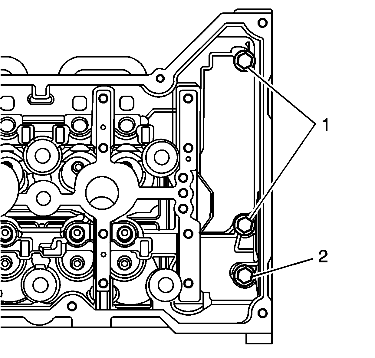
- Install the M6 cylinder head bolts at the front of the right cylinder head. Install the longer M6 cylinder head bolt (1) in the outboard location as shown. Install the two shorter M6 cylinder head bolts (3) in the locations shown.
- Tighten the M11 cylinder head bolts.
- Tighten the M11 cylinder head bolts a first pass in sequence to 40 N·m (30 lb ft).
- Tighten the M11 cylinder head bolts a second pass in sequence an additional 100 degrees using the J 36660-A .
- Tighten the M11 cylinder head bolts a final pass in sequence an additional 100 degrees (200 degrees total) using the J 36660-A .
- Tighten the long M6 cylinder head bolt (2).
- Tighten the two shorter M6 cylinder head bolts (1).
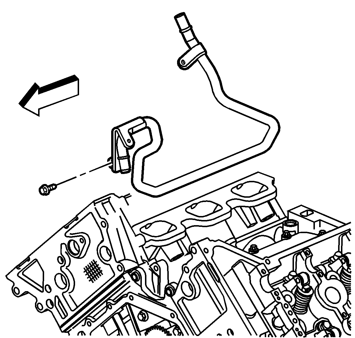
- Install the heater outlet pipe in the engine valley.
- Install the heater outlet pipe front bolt in the left cylinder head.
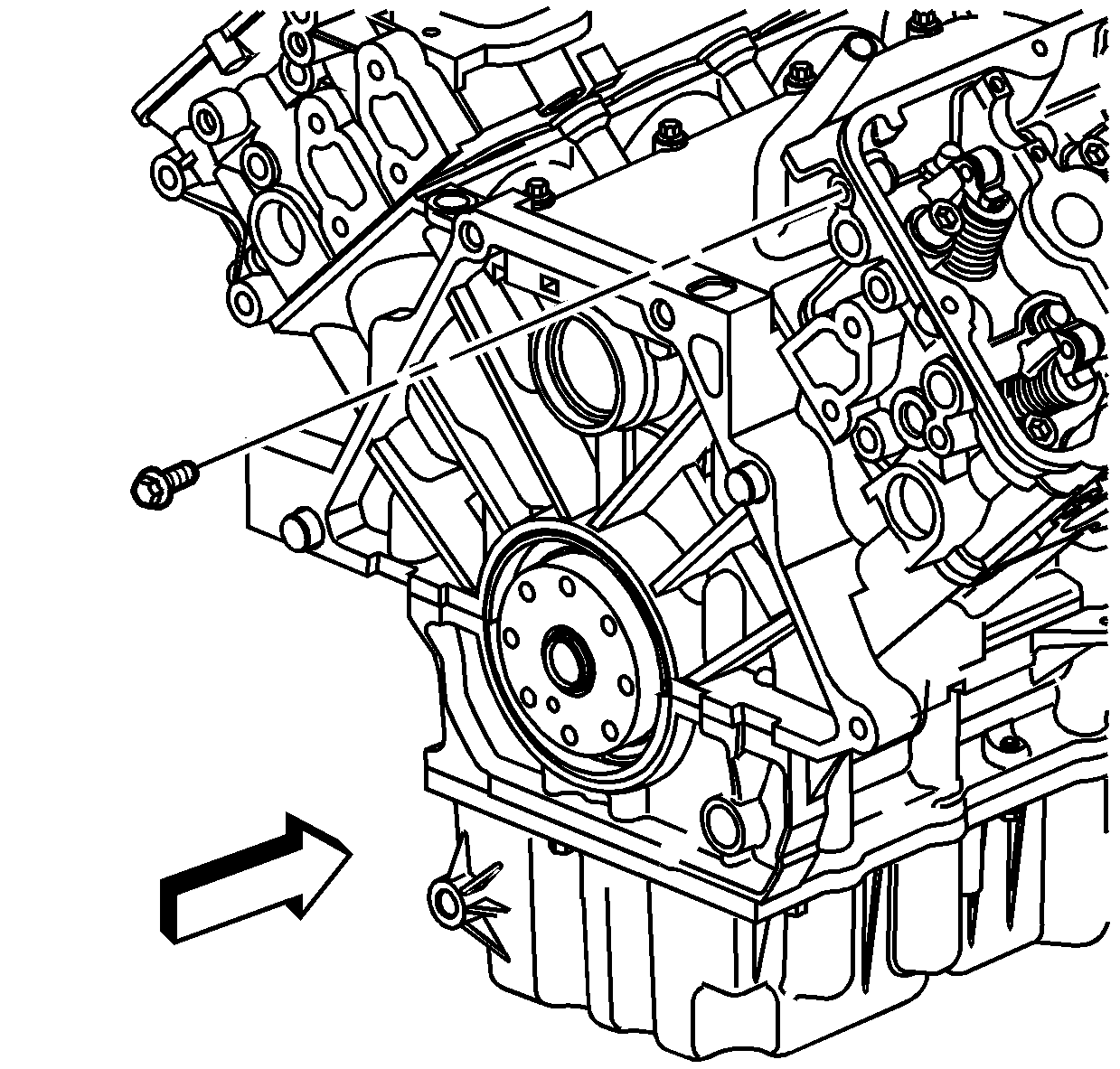
- Install the heater outlet pipe rear bolt in the right cylinder head.
Important: Ensure that the crankshaft is in the TDC position using the J 43032 .
Important: DO NOT reuse the old M11 cylinder head bolts.
Notice: Use the correct fastener in the correct location. Replacement fasteners must be the correct part number for that application. Fasteners requiring replacement or fasteners requiring the use of thread locking compound or sealant are identified in the service procedure. Do not use paints, lubricants, or corrosion inhibitors on fasteners or fastener joint surfaces unless specified. These coatings affect fastener torque and joint clamping force and may damage the fastener. Use the correct tightening sequence and specifications when installing fasteners in order to avoid damage to parts and systems.
Tighten
Tighten
Tighten the long M6 cylinder head bolt to 12 N·m (106 lb in).
Tighten
Tighten the two shorter M6 cylinder head bolts to 12 N·m
(106 lb in).
Tighten
Tighten the heater outlet pipe front bolt to 25 N·m (18 lb ft).
Tighten
Tighten the heater outlet pipe rear bolt to 25 N·m (18 lb ft).
