Removal Procedure
- Drain the engine coolant from the cooling system. Refer to Cooling System Draining and Filling in Engine Cooling.
- Remove the right diagonal brace. Refer to Front End Sheet Metal Diagonal Brace Replacement in Body Front End.
- Remove the battery hold-down retainer. Refer to Battery Hold Down Retainer Replacement in Engine Electrical.
- Remove the battery. Refer to Battery Replacement in Engine Electrical.
- Remove the battery tray. Refer to Battery Tray Replacement in Engine Electrical.
- Remove the engine coolant reservoir. Refer to Coolant Recovery Reservoir Replacement in Engine Cooling.
- Reposition the underhood accessory wiring junction block for access. Refer to Accessory Wiring Junction Block Replacement in Body Front End.
- Remove the drive belt. Refer to Drive Belt Replacement .
- Remove the power steering pump pulley. Refer to Power Steering Pump Pulley Replacement in Power Steering System.
- Remove the drive belt idler pulley.
- Remove the drive belt tensioner. Refer to Drive Belt Tensioner Replacement .
- Remove the engine front cover coolant drain plug and drain the coolant from the engine.
- Remove the water pump pulley retaining bolts.
- Remove the water pump pulley.
- Remove the water pump retaining bolts.
- Remove the water pump drive belt shield.
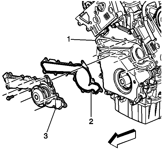
- Remove the water pump and housing (3) from the front cover (1). DO NOT damage the sealing surface.
- Remove the water pump gasket (2). Use a plastic scraper to remove any excess gasket material.
- The water pump and housing are one unit and must be serviced as an assembly.
- Support the cradle.
- Remove the right side cradle bolts. Refer to Frame Removal in Frame and Underbody.
- Lower the cradle.
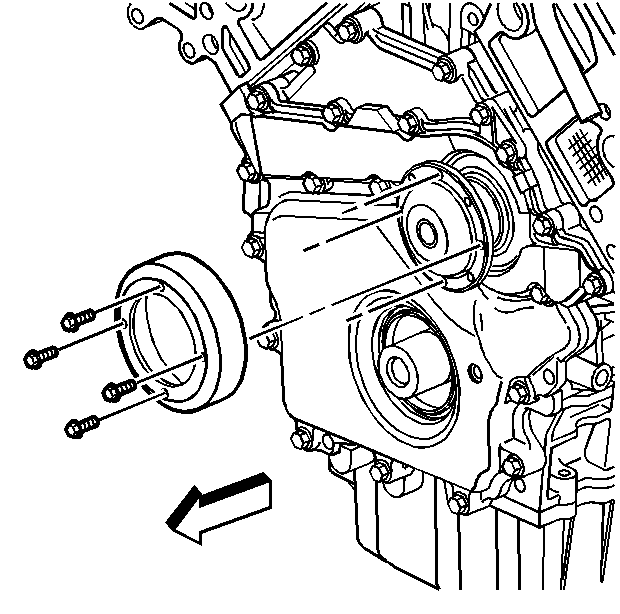
- Remove the crankshaft balancer. Refer to Crankshaft Balancer Replacement .
- Remove the ten front cover perimeter bolts.
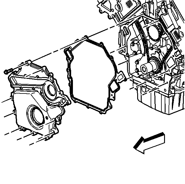
- Remove the front cover and the gasket. Make sure you do not damage the sealing surface. Some of the gasket material may remain on the engine block.
- Remove the remaining gasket material from the front cover and engine block using a plastic scraper.
Installation Procedure
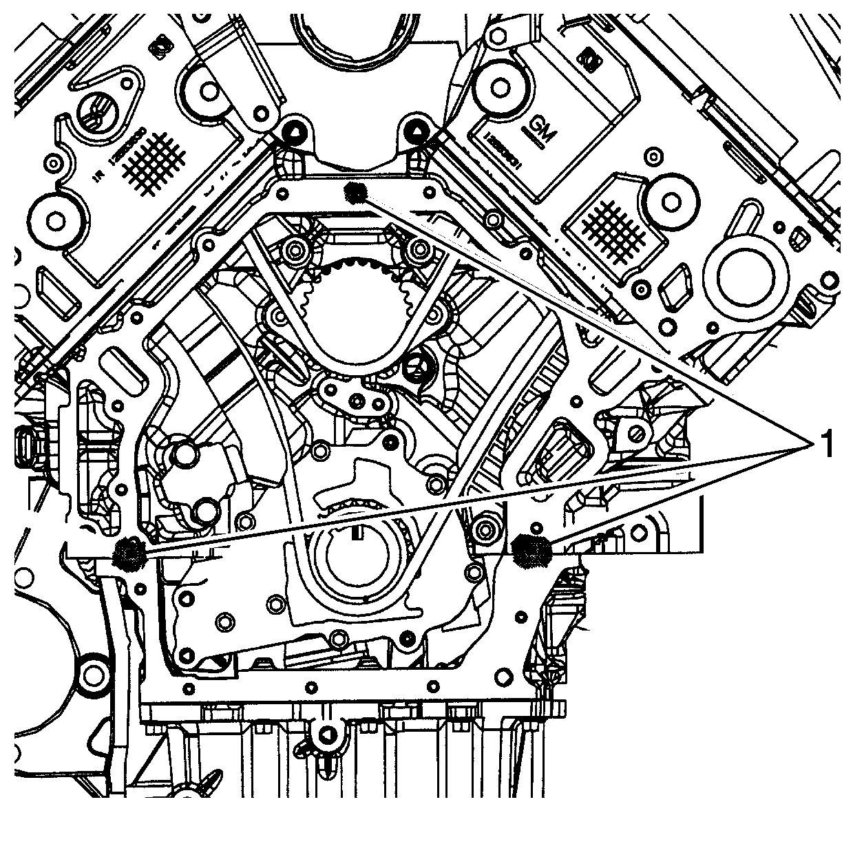
- Place a short bead of RTV sealant, GM P/N 12345739 or equivalent, on the cylinder block in the locations shown (1).
- Align front cover gasket to the front cover bolt holes and insert two bolts to hold the gasket in position.
- Install the front cover and gasket on the cylinder block.
- Hand start all the front cover retaining bolts.
- Install the crankshaft balancer. Refer to Crankshaft Balancer Replacement .
- Raise the cradle.
- Install the right side cradle bolts. Refer to Frame Removal in Frame and Underbody.
- Remove the cradle support.
- Make sure the front cover (1) and water pump (3) are clear of old gasket material.
- Place a new water pump gasket (2) on the water pump (3).
- Place the water pump in position on the front cover.
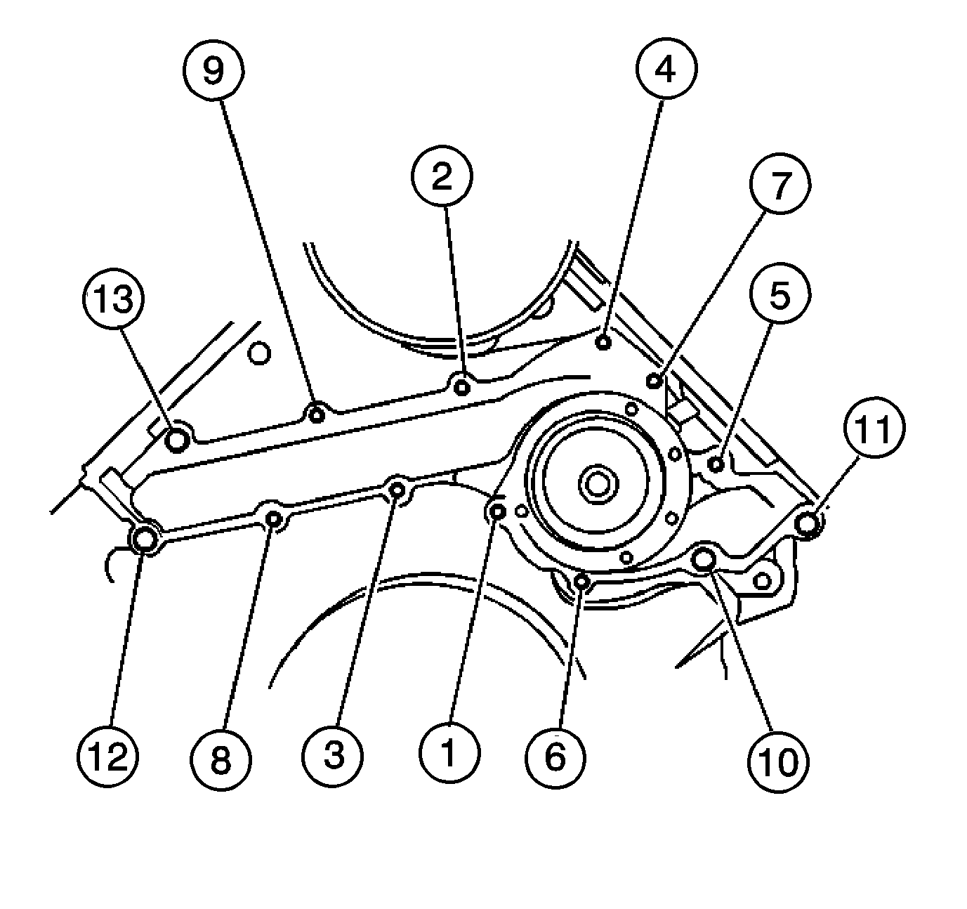
- Install the water pump retaining bolts in sequence.
- Install the water pump pulley and retaining bolts.
- Install the engine front cover coolant drain plug.
- Install the drive belt tensioner. Refer to Drive Belt Tensioner Replacement .
- Install the power steering pump pulley. Refer to Power Steering Pump Pulley Replacement in Power Steering System.
- Install the drive belt idler pulley.
- Install the drive belt. Refer to Drive Belt Replacement .
- Install the underhood accessory wiring junction block. Refer to Accessory Wiring Junction Block Replacement in Body Front End.
- Install the engine coolant reservoir. Refer to Coolant Recovery Reservoir Replacement in Engine Cooling.
- Install the battery tray. Refer to Battery Tray Replacement in Engine Electrical.
- Install the battery. Refer to Battery Replacement in Engine Electrical.
- Install the battery hold-down retainer. Refer to Battery Hold Down Retainer Replacement in Engine Electrical.
- Install the diagonal brace. Refer to Front End Sheet Metal Diagonal Brace Replacement in Body Front End.
- Fill the cooling system with engine coolant. Refer to Cooling System Draining and Filling in Engine Cooling.

Notice: Use the correct fastener in the correct location. Replacement fasteners must be the correct part number for that application. Fasteners requiring replacement or fasteners requiring the use of thread locking compound or sealant are identified in the service procedure. Do not use paints, lubricants, or corrosion inhibitors on fasteners or fastener joint surfaces unless specified. These coatings affect fastener torque and joint clamping force and may damage the fastener. Use the correct tightening sequence and specifications when installing fasteners in order to avoid damage to parts and systems.
Tighten
Tighten the front cover retaining bolts to 14 N·m (124 lb in).


Tighten
Tighten the water pump bolts to 14 N·m (124 lb in).

Tighten
Tighten the water pump pulley bolts to 12 N·m (106 lb in).
Tighten
Tighten the engine front cover coolant drain plug to 10 N·m
(89 lb in).
