Exhaust Manifold Installation Right
- Install the right engine coolant heater.
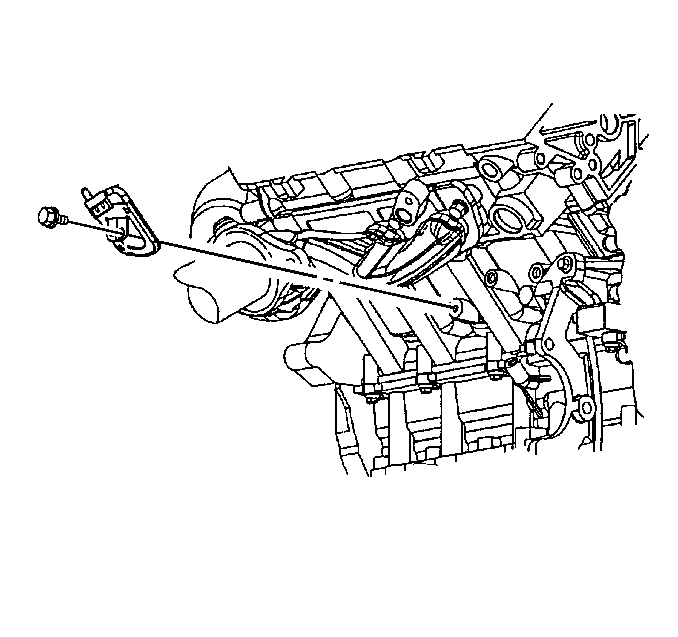
- Install the right engine coolant heater bolt.
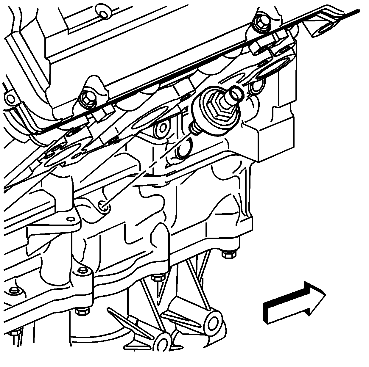
- Install the knock sensor.
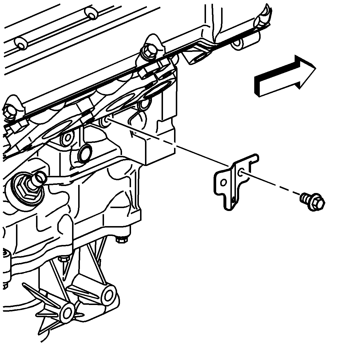
- Install the wiring harness bracket.
- Install the wiring harness bracket bolt.
- Install the oil pressure switch.
- Install the ECT sensor.
- Install the engine wiring harness.
- Connect the engine wiring harness to the ECT sensor.
- Install the engine wiring harness to the lower crankcase.
- Connect the engine wiring harness to the knock sensor.
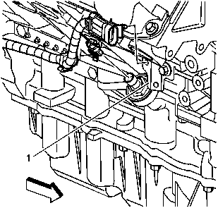
- Install the engine wiring harness to the wiring harness bracket (1).
- Position a new exhaust manifold gasket onto the right exhaust manifold.
- Install the exhaust manifold bolts.
- Place the right exhaust manifold, exhaust manifold gasket and bolts as an assembly in position on the right cylinder head.
- Install the exhaust manifold bolts into the right cylinder head.
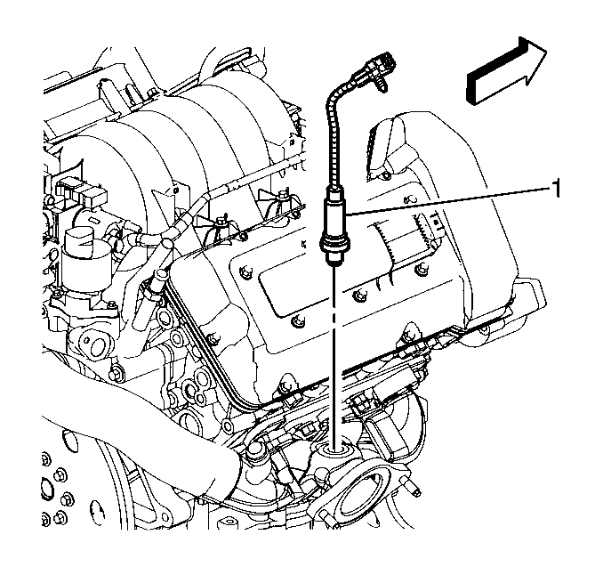
- Coat the oxygen sensor threads with anti-seize such as GM P/N 5613695 or equivalent.
- Install the oxygen sensor (1).
- Install the NEW EGR valve inlet pipe (1).
- Loosely install the EGR valve inlet pipe nut (3) to the exhaust crossover pipe.
- Install the EGR valve inlet pipe bolt (2) to the water crossover pipe.
- Install the EGR valve inlet pipe nut (3) to the exhaust crossover pipe.
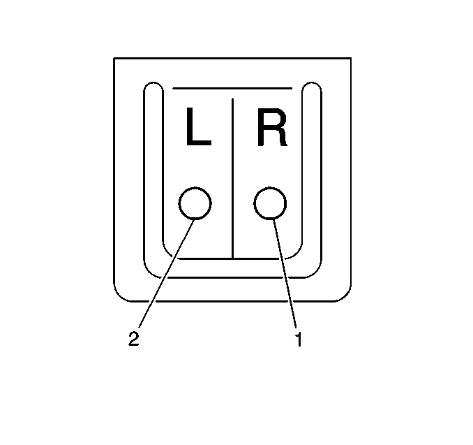
Important: Align the threaded hole in the engine block with the hole labeled R (1) on the right coolant heater.
Notice: Use the correct fastener in the correct location. Replacement fasteners must be the correct part number for that application. Fasteners requiring replacement or fasteners requiring the use of thread locking compound or sealant are identified in the service procedure. Do not use paints, lubricants, or corrosion inhibitors on fasteners or fastener joint surfaces unless specified. These coatings affect fastener torque and joint clamping force and may damage the fastener. Use the correct tightening sequence and specifications when installing fasteners in order to avoid damage to parts and systems.
Tighten
Tighten the right coolant heater bolt to 9 N·m (80 lb in).
Tighten
Tighten the knock sensor to 15 N·m (11 lb ft).
Tighten
Tighten the wiring harness bracket bolt to 25 N·m (18 lb ft).
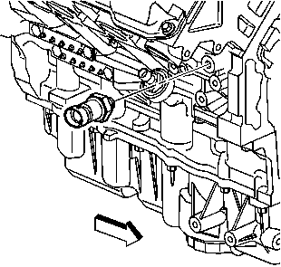
Tighten
Tighten the oil pressure switch to 10 N·m (89 lb in).
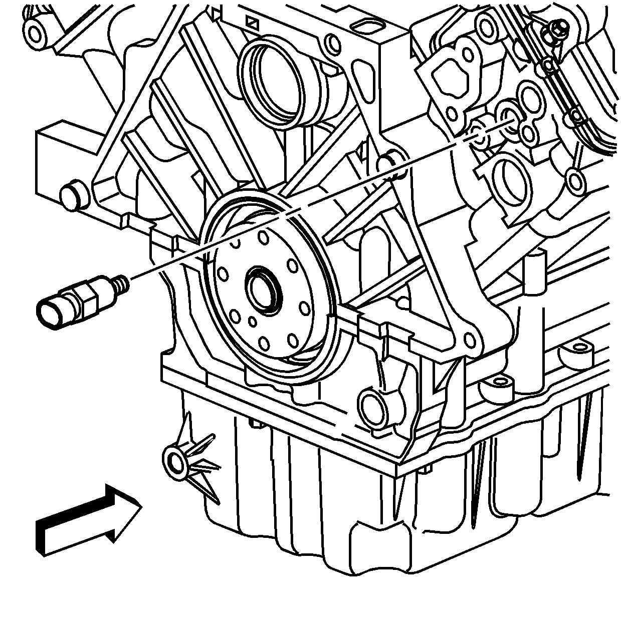
Tighten
Tighten the ECT sensor to 20 N·m (15 lb ft).
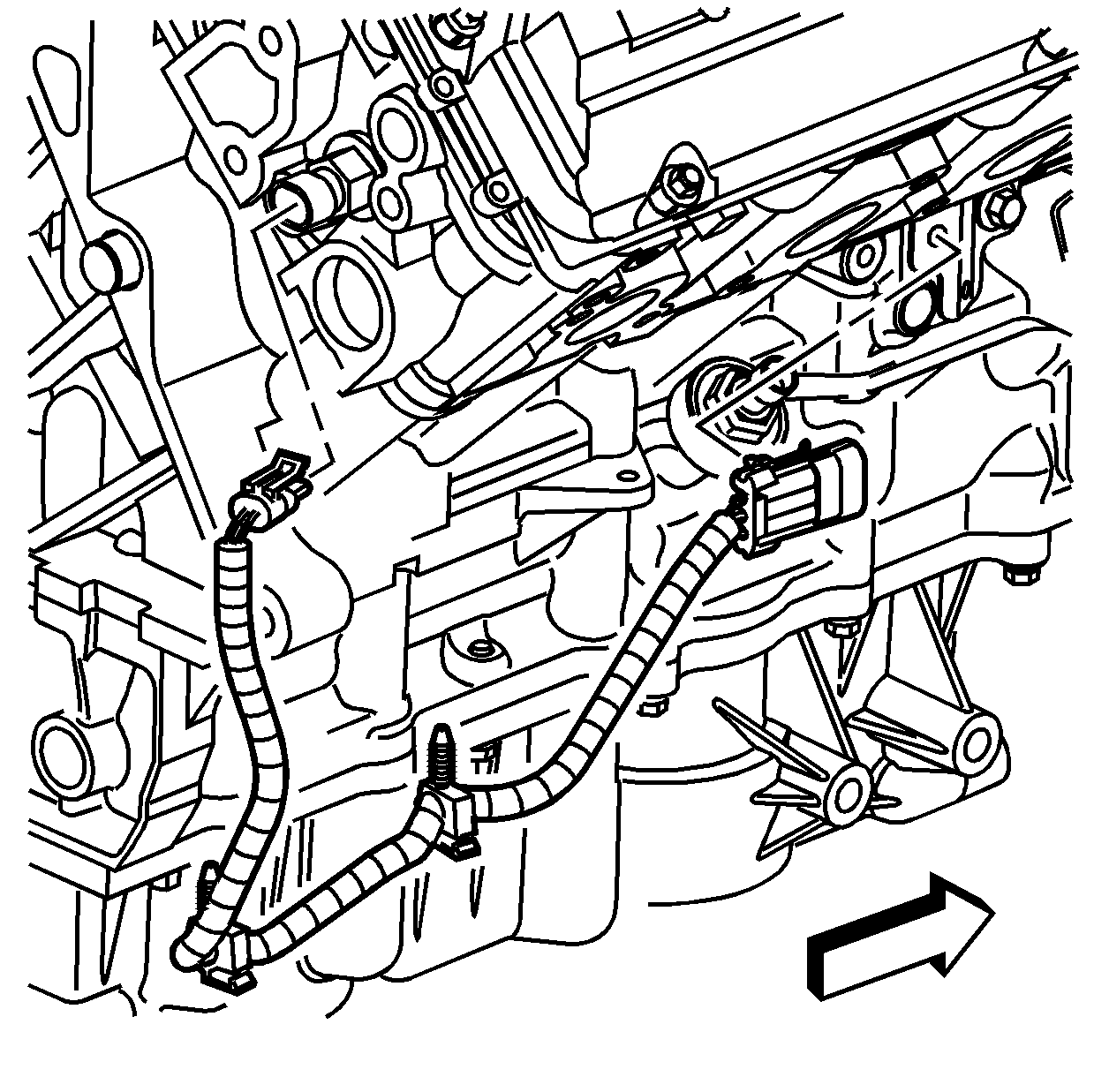
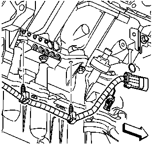
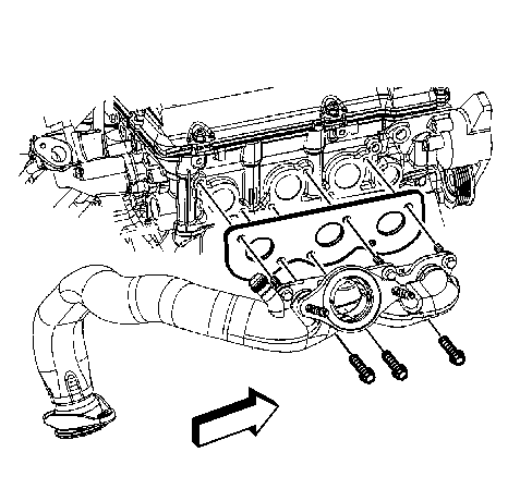
Important: Installing the exhaust manifold/crossover pipe assembly with the engine on an engine stand is difficult. Remove the engine from the engine stand and install the exhaust manifold with the engine properly supported on the floor or on a bench.
Important: You MUST use a new exhaust manifold gasket when installing the exhaust manifold.
Tighten
Tighten the right exhaust manifold bolts to 25 N·m (18 lb ft).
Tighten
Tighten the oxygen sensor to 41 N·m (30 lb ft).
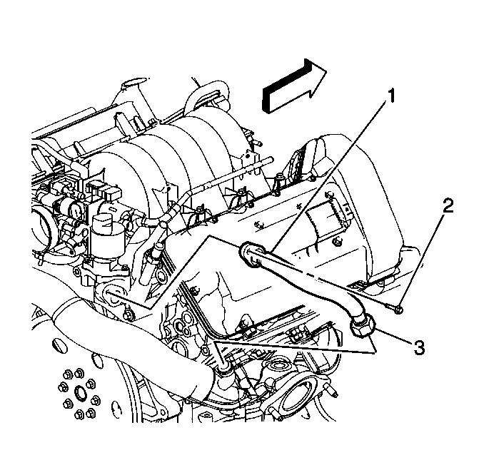
Important: The EGR valve inlet pipe incorporates a crush seal connection at the water crossover. The EGR valve inlet pipe must be replaced if disconnected from the water crossover.
Tighten
Tighten the EGR valve inlet pipe bolt to 24 N·m (18 lb ft).
Tighten
Tighten the EGR valve inlet pipe nut to 60 N·m (44 lb ft).
Exhaust Manifold Installation Left
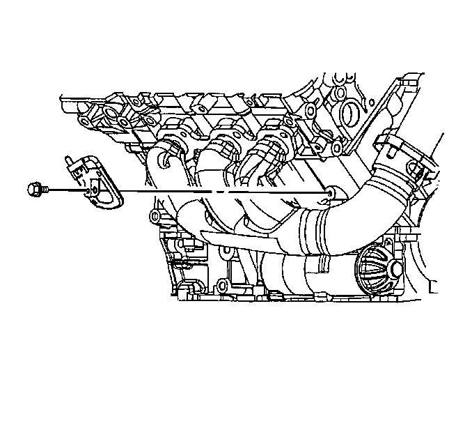
- Install the left engine coolant heater.
- Install the left engine coolant heater bolt.
- Install a NEW manifold to crossover flange gasket onto the left exhaust manifold flange.
- Position a NEW exhaust manifold gasket onto the left exhaust manifold.
- Install the exhaust manifold bolts into the left exhaust manifold.
- Install the left exhaust manifold to the crossover pipe from the right exhaust manifold and up to the left cylinder head.
- Install the exhaust manifold bolts into the left cylinder head.
- Install the left exhaust manifold to crossover pipe flange bolts.
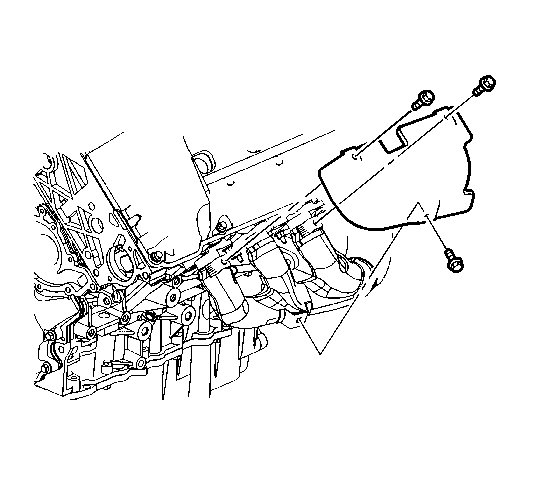
- Place the exhaust manifold heat shield in position.
- Install the exhaust manifold heat shield bolts.
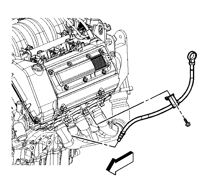
- Install a NEW O-ring on the oil level indicator tube.
- Install the oil level indicator and tube by sliding the tube down through the exhaust manifold and fitting the end into lower crankcase hole.
- Install the oil level indicator tube bolt.

Important: Align the threaded hole in the engine block with the hole labeled L (2) on the left coolant heater.
Notice: Use the correct fastener in the correct location. Replacement fasteners must be the correct part number for that application. Fasteners requiring replacement or fasteners requiring the use of thread locking compound or sealant are identified in the service procedure. Do not use paints, lubricants, or corrosion inhibitors on fasteners or fastener joint surfaces unless specified. These coatings affect fastener torque and joint clamping force and may damage the fastener. Use the correct tightening sequence and specifications when installing fasteners in order to avoid damage to parts and systems.
Tighten
Tighten the left coolant heater bolt to 9 N·m (80 lb in).
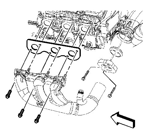
Important: Installing the exhaust manifold/crossover pipe assembly with the engine on an engine stand is difficult. Remove the engine from the engine stand and install the exhaust manifold with the engine properly supported on the floor or on a bench.
Important: You must install a NEW crossover flange gasket.
Notice: Use the correct fastener in the correct location. Replacement fasteners must be the correct part number for that application. Fasteners requiring replacement or fasteners requiring the use of thread locking compound or sealant are identified in the service procedure. Do not use paints, lubricants, or corrosion inhibitors on fasteners or fastener joint surfaces unless specified. These coatings affect fastener torque and joint clamping force and may damage the fastener. Use the correct tightening sequence and specifications when installing fasteners in order to avoid damage to parts and systems.
Tighten
Tighten the exhaust manifold bolts to 25 N·m (18 lb ft).
Tighten
Tighten the left exhaust manifold to crossover flange bolts to 25 N·m
(18 lb ft).
Tighten
Tighten the exhaust manifold heat shield bolts to 9 N·m
(80 lb in).
Tighten
Tighten the oil level indicator tube bolt to 9 N·m (80 lb in).
Exhaust Manifold Installation Left with RPO NB7
- Install the left engine coolant heater.
- Install the left engine coolant heater retainer bolt.
- Install a NEW manifold to crossover flange gasket onto the left exhaust manifold flange.
- Position a NEW exhaust manifold gasket onto the left exhaust manifold.
- Install the exhaust manifold bolts into the left exhaust manifold.
- Install the left exhaust manifold to the crossover pipe from the right exhaust manifold and up to the left cylinder head.
- Install the exhaust manifold retaining bolts into the left cylinder head.
- Install the left exhaust manifold to crossover pipe flange retaining bolts.
- Place the exhaust manifold heat shield in position.
- Install the exhaust manifold heat shield retaining bolts.
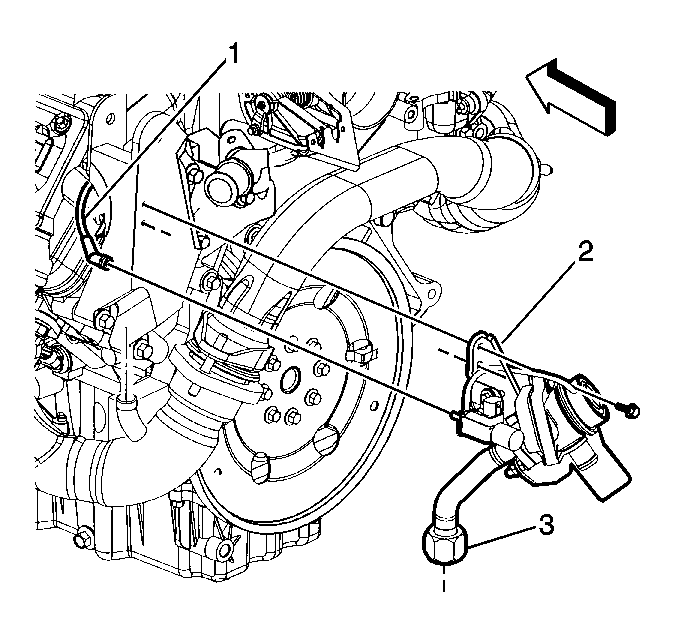
- Connect the A.I.R. feed pipe nut (3) to the exhaust manifold.
- Install the A.I.R. control valve retaining bolts to the torque strut bracket.
- Install the feed pipe nut (3).
- Connect the vacuum tube (1) to the A.I.R. control valve.
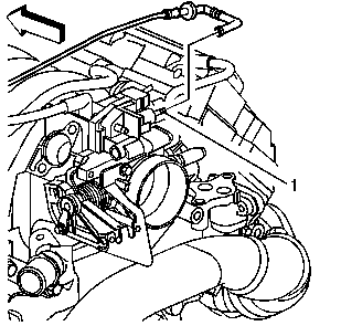
- Connect the A.I.R. vacuum hose to the throttle body.
- Install the A.I.R. vacuum hose to the retaining clip on the engine lift bracket.
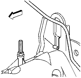
- Install a NEW O-ring on the oil level indicator tube.
- Install the oil level indicator and tube by sliding the tube down through the exhaust manifold and fitting the end into lower crankcase hole.
- Install the oil level indicator tube retaining bolt.

Important: Align the threaded hole in the engine block with the hole labeled L (2) on the left coolant heater.

Notice: Use the correct fastener in the correct location. Replacement fasteners must be the correct part number for that application. Fasteners requiring replacement or fasteners requiring the use of thread locking compound or sealant are identified in the service procedure. Do not use paints, lubricants, or corrosion inhibitors on fasteners or fastener joint surfaces unless specified. These coatings affect fastener torque and joint clamping force and may damage the fastener. Use the correct tightening sequence and specifications when installing fasteners in order to avoid damage to parts and systems.
Tighten
Tighten the left coolant heater bolt to 9 N·m (80 lb in).

Important: Installing the exhaust manifold/crossover pipe assembly with the engine on an engine stand is difficult. Remove the engine from the engine stand and install the exhaust manifold with the engine properly supported on the floor or on a bench.
Important: You must install a NEW crossover flange gasket.
Notice: Use the correct fastener in the correct location. Replacement fasteners must be the correct part number for that application. Fasteners requiring replacement or fasteners requiring the use of thread locking compound or sealant are identified in the service procedure. Do not use paints, lubricants, or corrosion inhibitors on fasteners or fastener joint surfaces unless specified. These coatings affect fastener torque and joint clamping force and may damage the fastener. Use the correct tightening sequence and specifications when installing fasteners in order to avoid damage to parts and systems.
Tighten
Tighten the exhaust manifold retaining bolts to 25 N·m
(18 lb ft).
Tighten
Tighten the left exhaust manifold to crossover flange bolts to 25 N·m
(18 lb ft).

Tighten
Tighten the exhaust manifold heat shield retaining bolts to 9 N·m
(80 lb in).
Tighten
Tighten the control valve retaining bolts to 9 N·m (80 lb in).
Tighten
Tighten the feed pipe nut to 60 N·m (44 lb ft).

Tighten
Tighten the oil level indicator retaining bolt to 9 N·m
(80 lb in).
