Tools Required
J 36660-A Torque/Angle Meter
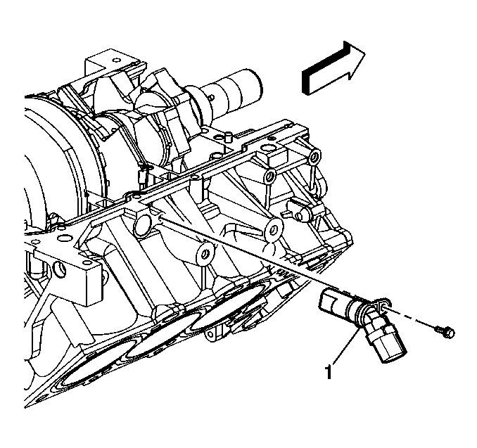
- Install a NEW O-ring on the crankshaft position sensor.
- Lubricate the O-ring with clean engine oil.
- Install the crankshaft position sensor (1).
- Install the crankshaft position sensor bolt.
- Wipe all sealing surfaces clean with a dry, lint-free cloth.
- Work new upper-to-lower crankcase seals (1) into their grooves starting at both ends and working the seal towards the center. The seal must not be torn, nicked, or out of the groove over its entire length on both sides of the crankcase.
- Apply a thin bead (2) of Gasket Maker, GM P/N US 1052942, Canada 10953466, 6 ML or US 1052943, Canada 10953491, 50 ML or equivalent, to the upper crankcase. From the front of the block apply a bead 1-2 mm thick (0.040-0.080 in) inline with the silicone seal (1) and through the centerline of the bolt holes but not through the bolt holes. Continue applying the bead until the end of the crankcase at the back of the block. Do not apply the bead all the way to the crankshaft rear oil seal.
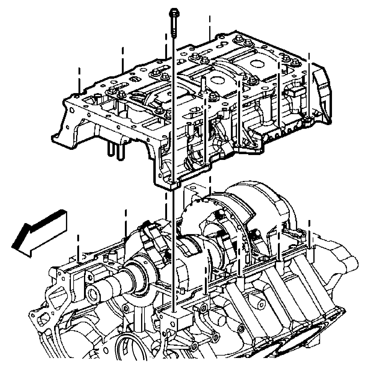
- Place the crankshaft oil scraper (2) in position on the lower crankcase. Align the holes with the main bearing bolt holes.
- Place into position the main bearing bolts. The single stud-head bolt (1) is used for oil pump pick-up mounting.
- Align the lower crankcase with the dowel pins in the upper crankcase.
- Install the lower crankcase onto the upper crankcase slowly until feeling a positive stop.
- Inspect the upper-to-lower crankcase joint to make sure the lower crankcase is fully seated on the cylinder block.
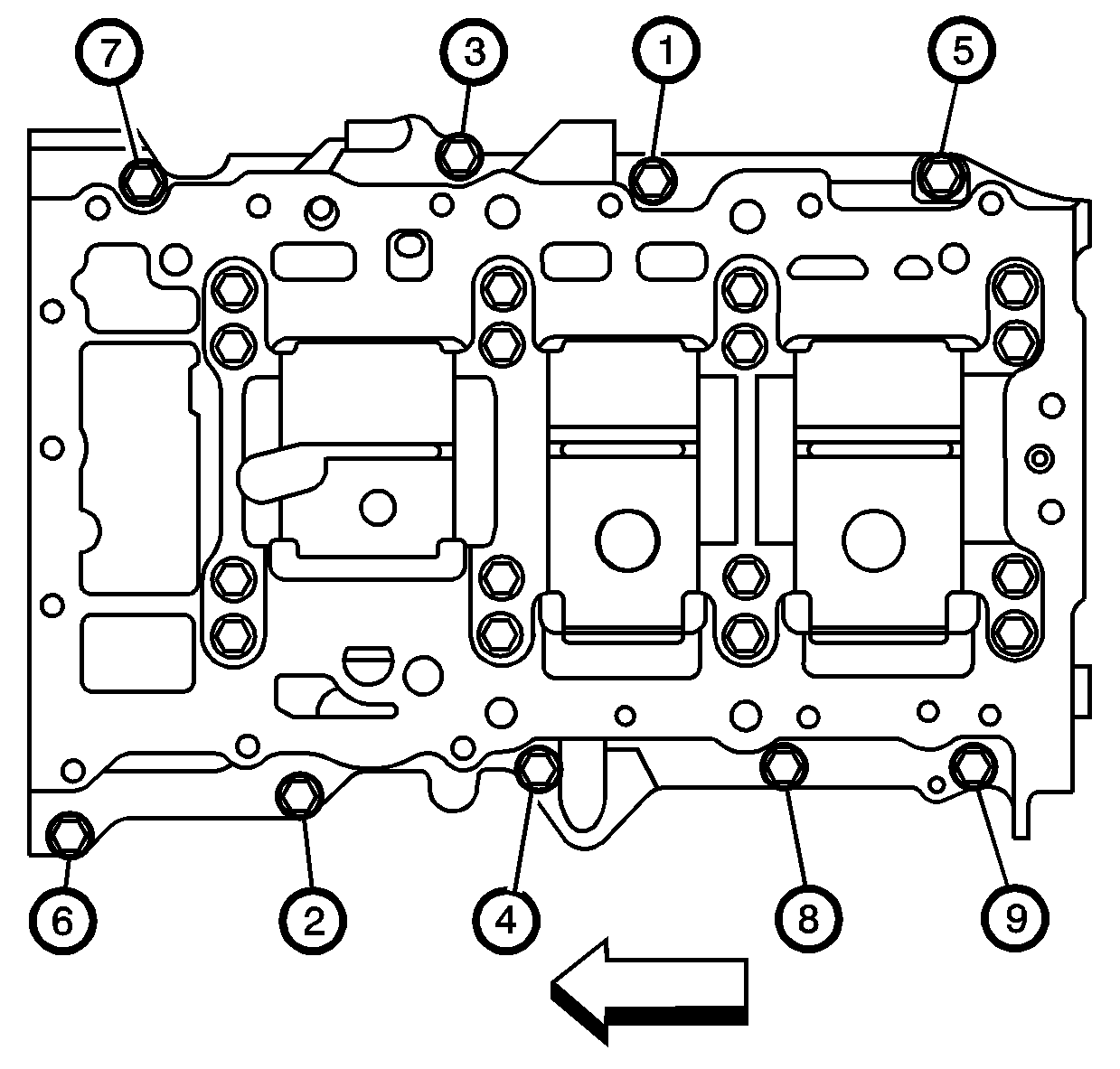
- Loosely install the nine lower crankcase perimeter bolts.
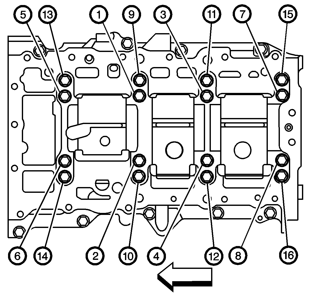
- Tighten the lower crankcase bolts (1 through 16) in proper sequence.
- Tighten the lower crankcase bolts in sequence to 20 N·m (15 lb ft).
- Tighten the lower crankcase bolts in sequence an additional 70 degrees using the J 36660-A .
- Tighten the lower crankcase perimeter bolts (1 through 9) in proper sequence.
Notice: Use the correct fastener in the correct location. Replacement fasteners must be the correct part number for that application. Fasteners requiring replacement or fasteners requiring the use of thread locking compound or sealant are identified in the service procedure. Do not use paints, lubricants, or corrosion inhibitors on fasteners or fastener joint surfaces unless specified. These coatings affect fastener torque and joint clamping force and may damage the fastener. Use the correct tightening sequence and specifications when installing fasteners in order to avoid damage to parts and systems.
Tighten
Tighten the crankshaft position sensor bolt to 9 N·m (80 lb in).
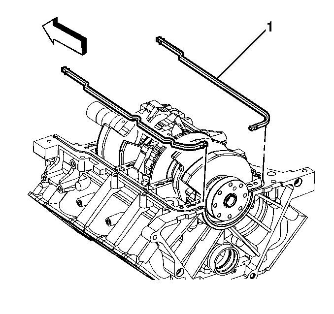
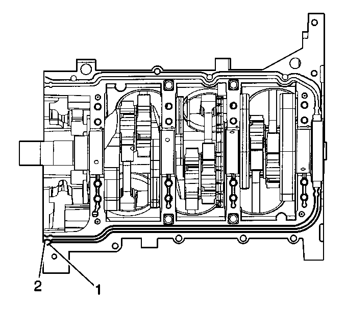
Important: Do not allow the sealant into the bolt holes. Sealant in the bolt holes will inhibit proper torquing of the bolts due to hydraulic locking.
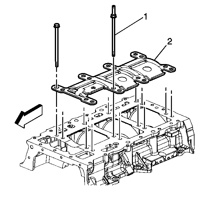
Important: The crankshaft oil scraper is stamped with an arrow for the front of engine.
Important: The crankshaft oil scraper is stamped for the location of the single stud-head bolt.
Tighten
Tighten
Tighten the lower crankcase perimeter bolts in sequence to 30 N·m
(22 lb ft).
