For 1990-2009 cars only
The pinion clearance cannot be adjusted. Improper clearance is an indication of worn parts. The following procedure describes the pinion clearance inspection:
- Secure the starter motor in a vise or equivalent fixture so that the opening in the drive end housing is accessible for measurement.
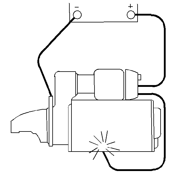
- Disconnect the starter motor field lead from the solenoid M terminal.
- Insulate the starter motor field lead from the solenoid M terminal.
- Connect the battery ground (negative) lead to a clean metal ground on the motor housing.
- Connect a 12 volt battery lead to the solenoid S terminal.
- Momentarily ground a jumper lead from the solenoid M terminal to the solenoid frame. This will shift the pinion into the cranking position. The pinion will remain in the cranking position until the jumper lead is removed.
- Push the pinion back toward the commutator end to eliminate any free movement of the pinion on the shaft.
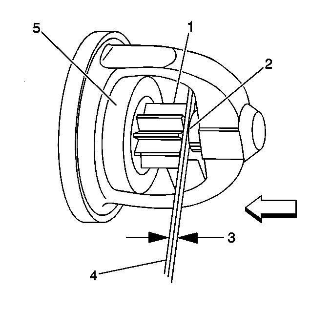
- Measure the distance between the pinion (1) and the pinion stop collar (2) using feeler gauges.
- Disconnect the battery ground (negative) lead from the starter motor housing (the pinion will retract), then disconnect the positive lead from the solenoid S terminal.
- Replace the starter motor when the clearance is outside the specifications.
Caution: Keep fingers, tools, and any other objects away from the opening in the drive end housing while making electrical connections. The strong shifting action of the starter solenoid can cause severe personal injury or damage to components as the drive pinion moves into the cranking position.

Notice: To prevent overheating of the solenoid pull-in winding, do not leave the winding energized for more than 15 seconds. The current draw will decrease as the winding temperature increases.

The clearance should be from 0.25-4.06 mm (0.010-0.160 in).
