Electrical Connector Replacement for Oldsmobile Intrigue 1999
Electrical Connector Replacement 3.5L Twin Cam V6 LX5
Removal Procedure
- Remove the case side cover. Refer to
Control Valve Body Cover Replacement
.
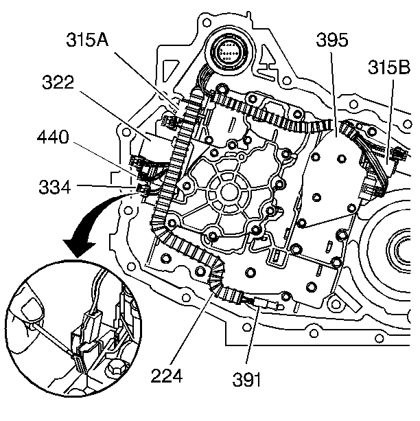
- Disconnect the wiring
harness assembly (224) from the following components:
| • | TFP manual valve position switch (395) |
| • | 1-2 shift solenoid (315A) |
| • | 2-3 shift solenoid (315B) |
| • | Torque converter clutch PWM solenoid (334) |
| • | Pressure control solenoid (322) |
| • | Input speed sensor (440) |
| • | Fluid temperature sensor (391) |
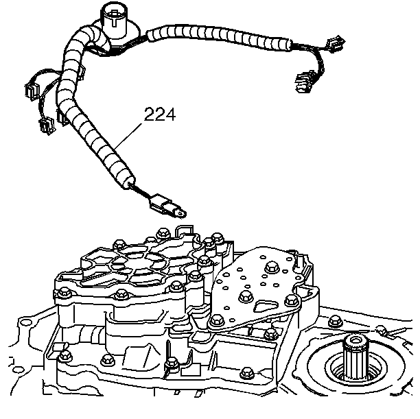
- Remove the wiring harness
assembly (224).
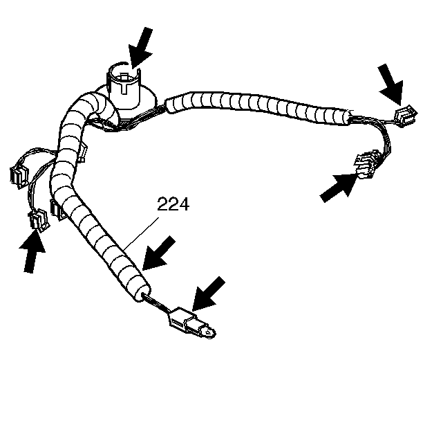
- Inspect the wiring harness
assembly (224) for:
| • | Bent or broken electrical connections |
Installation Procedure
- Install the wiring harness
assembly (224).
- Connect the wiring harness
assembly (224) to the following components:
| • | TFP manual valve position switch (395) |
| • | 1-2 shift solenoid (315A) |
| • | 2-3 shift solenoid (315B) |
| • | Torque converter clutch PWM solenoid (334) |
| • | Pressure control solenoid (322) |
| • | Input speed sensor (440) |
| • | Fluid temperature sensor (391) |
- Install the case side cover. Refer to
Control Valve Body Cover Replacement
.
Electrical Connector Replacement 3800 L36
Removal Procedure
- Remove the case side cover. Refer to
Control Valve Body Cover Replacement
.
- Disconnect the wiring
harness assembly (224) from the following components:
| • | TFP manual valve position switch (395) |
| • | 1-2 shift solenoid (315A) |
| • | 2-3 shift solenoid (315B) |
| • | Torque converter clutch PWM solenoid (334) |
| • | Pressure control solenoid (322) |
| • | Input speed sensor (440) |
| • | Fluid temperature sensor (391) |
- Remove the wiring harness
assembly (224).
- Inspect the wiring harness
assembly (224) for:
| • | Bent or broken electrical connections |
Installation Procedure
- Install the wiring harness
assembly (224).
- Connect the wiring harness
assembly (224) to the following components:
| • | TFP manual valve position switch (395) |
| • | 1-2 shift solenoid (315A) |
| • | 2-3 shift solenoid (315B) |
| • | Torque converter clutch PWM solenoid (334) |
| • | Pressure control solenoid (322) |
| • | Input speed sensor (440) |
| • | Fluid temperature sensor (391) |
- Install the case side cover. Refer to
Control Valve Body Cover Replacement
.
