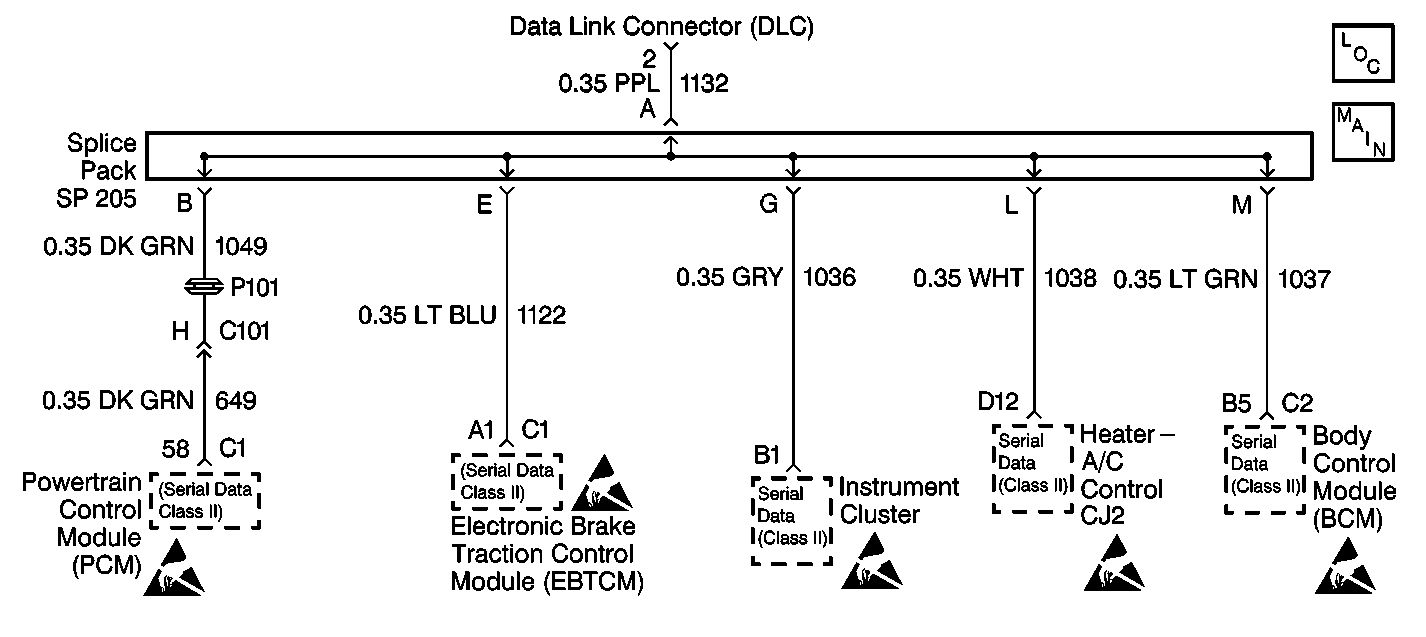
For 1990-2009 cars only

Circuit Description
Class 2 control modules interface with each other through the class 2 serial data link.
Conditions for Setting the DTC
Class 2 control modules detect a short to ground in the class 2 serial data link.
Action Taken When the DTC Sets
| • | The SERVICE VEHICLE SOON indicator lamp turns on. |
| • | Class 2 control modules store DTC U1300 in memory. |
Conditions for Clearing the DTC
| • | Class 2 control modules no longer detect a short to ground in the class 2 serial data link. |
| • | Class 2 control modules monitor their own transmitted message over the class 2 serial data link. |
| • | Using a scan tool. |
Diagnostic Aids
| • | DTC U1300 indicates that the class 2 serial data link has been shorted to ground. The class 2 control modules send DTC information to a scan tool via the class 2 serial data link. If the class 2 serial data link is currently shorted to ground, the scan tool will be unable to communicate with any class 2 control module. Therefore, you will be unable to obtain a DTC U1300 as a current DTC. However, if the scan tool is able to communicate with a class 2 control module and DTC U1300 is read, it will be a history DTC. Wiggle wires and connectors when performing circuit checks on the class 2 serial data link. This can often cause the short to ground to reappear. |
| • | The following conditions may cause an intermittent malfunction to occur: |
| - | An intermittent short to ground in the class 2 serial data link. |
| - | A class 2 control module is shorted to ground internally. |
| • | DTC P1626 will set in the Powertrain Control Module (PCM) when the ignition switch is on with the Body Control Module (BCM) disconnected. When BCM diagnostics and repairs are completed, refer to Engine Controls for additional information on PCM related DTCs. |
Test Description
The number below refers to the step number on the diagnostic table.
Step | Action | Value(s) | Yes | No | ||||||||||||
|---|---|---|---|---|---|---|---|---|---|---|---|---|---|---|---|---|
1 | Was the Data Link Connector system check performed? | -- | ||||||||||||||
Does this DTC reset? | -- | Go to Diagnostic Aids | ||||||||||||||
3 | The class 2 serial data link is not shorted. However, the module setting this DTC is malfunctioning. For further diagnosis and repair, refer to:
Is the action complete? | -- | -- | |||||||||||||
4 |
Is the action complete? | -- | System OK | -- |
