Circuit Description
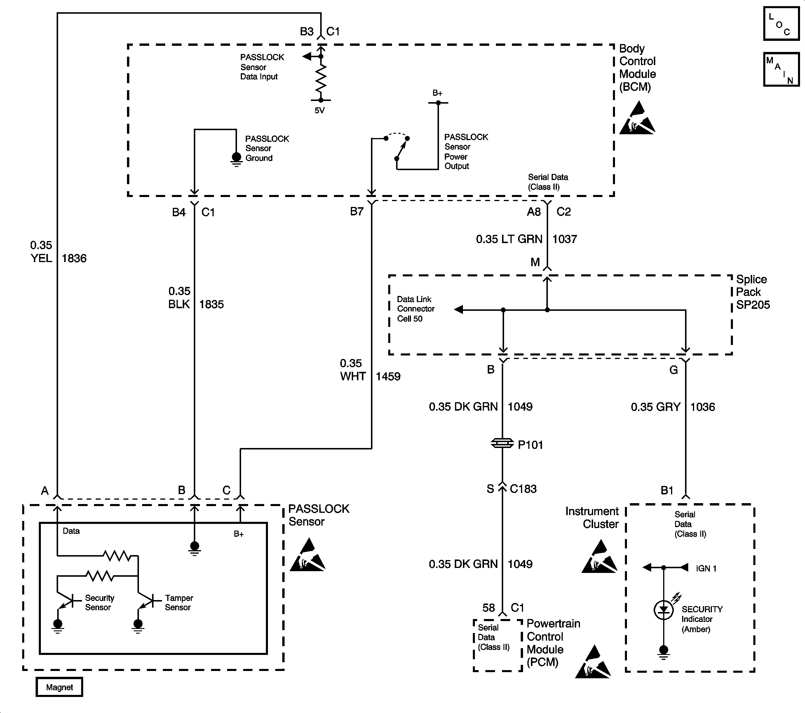
The Passlock theft deterrent system contains a Passlock sensor. The Passlock sensor is part of the ignition lock cylinder assembly. The Body Control Module (BCM) provides voltage (B+) to the Passlock sensor through circuit 1459 when the ignition switch is in the accessory, on, or start. The BCM also provides ground to the Passlock sensor through circuit 1835. The Passlock sensor interfaces with the BCM through the Passlock detection circuit 1836.
When turning the ignition switch to the start position with the proper key, the Passlock sensor generates an analog voltage signal. This signal is sent through the Passlock detecting circuit. This analog voltage signal is of a specific value to the vehicle, and varies from vehicle to vehicle. When attempting to start the engine, the BCM compares a preset stored analog voltage value with the signal coming from the sensor. Because both values match, the BCM sends a fuel enable password via the Class II serial data link to the Powertrain Control Module (PCM). As a result, the PCM enables the crank relay, and allows fuel delivery to the engine.
When attempting to start the engine by means other than using the proper key in the ignition switch, the Passlock sensor sends an analog voltage signal of a different value. The BCM compares the preset stored analog voltage value with the signal coming from the sensor. Because both values do not match, the BCM sends a fuel disable password via the Class II serial data link to the Powertrain Control Module (PCM). As a result, the PCM disables the crank relay, and does not allow fuel delivery to the engine.
Conditions for Setting the DTC
The BCM detects a short to ground in circuit 1459 for one second with the ignition switch in the accessory, on, or start.
Action Taken When the DTC Sets
| • | The BCM stores DTC B2947 in memory. |
| • | The BCM sends a message to the instrument cluster to turn ON the SECURITY indicator. |
| • | In addition, the BCM will take one of two actions: |
| 1. | If circuit 1459 is either shorted to ground when attempting to start the engine, the BCM will NOT send a message to the PCM to enable the crank relay, and to deliver fuel to the engine. The vehicle will exhibit an engine no crank condition, OR |
| 2. | If circuit 1459 is shorted to ground after the engine has started, the BCM enters a fail-enable mode. Upon subsequent engine start attempts, the BCM will send a password message to the PCM via the Class II serial data link to enable the crank relay, and to deliver fuel to the engine. The engine will start. |
Conditions for Clearing the DTC
| • | When a short to ground is no longer present in circuit 1459, the ignition switch must be cycled from off to accessory before this DTC can change from a current DTC to a history DTC. |
| • | The BCM no longer detects a short to ground in circuit 1459. |
| • | A history DTC will clear after 100 consecutive ignition cycles if the condition for the malfunction is no longer present. |
| • | Using a scan tool. Refer to Clearing DTCs |
Diagnostic Aids
| • | Check for a short between circuit 1459 and 1835, or a short to ground in circuit 1459. |
| • | The following conditions may cause an intermittent malfunction to occur: |
| - | A faulty (shorted) Passlock sensor. |
| - | An intermittent short to ground in circuit 1459. |
| - | An intermittent short between circuit 1459 and circuit 1835; the BCM would interpret this as a short to ground condition. |
| • | If this DTC is a history DTC, the problem may be intermittent. Try performing the tests shown while moving wiring, connectors, and the key, this can often cause the malfunction to appear. |
| • | DTC P1626 will set in the Powertrain Control Module (PCM) when the ignition switch is on with the Body Control Module (BCM) disconnected. When BCM diagnostics and repairs are completed, refer to Powertrain On Board Diagnostic (OBD) System Check (LX5) or Powertrain On Board Diagnostic (OBD) System Check (L36) in Engine Controls for additional information on PCM related DTCs. |
Test Description
The number(s) below refer to the step number(s) on the diagnostic table.
-
Always perform the BCM diagnostic system check before attempting to diagnose this DTC.
-
Checks for a short to ground in circuit 1459.
-
Determines whether the BCM or the PASSLOCK sensor is internally shorted to ground.
-
Perform the Setup New BCM procedure after repairs for proper BCM operation.
-
Refer to the Theft Deterrent Re-Learn procedure after repair for proper BCM operation.
Step | Action | Value(s) | Yes | No |
|---|---|---|---|---|
Was the BCM diagnostic system check performed? | ||||
Is the resistance measured same as the specified range? | Infinite | |||
Is the voltage within the specified range? | B+ (10-14V) | |||
4 | Repair short to ground in circuit 1459. Is the repair complete? | -- | -- | |
Is the repair complete? | -- | -- | ||
Is the repair complete? | -- | -- | ||
7 |
Are there any current BCM DTCs present? | -- | System OK |
