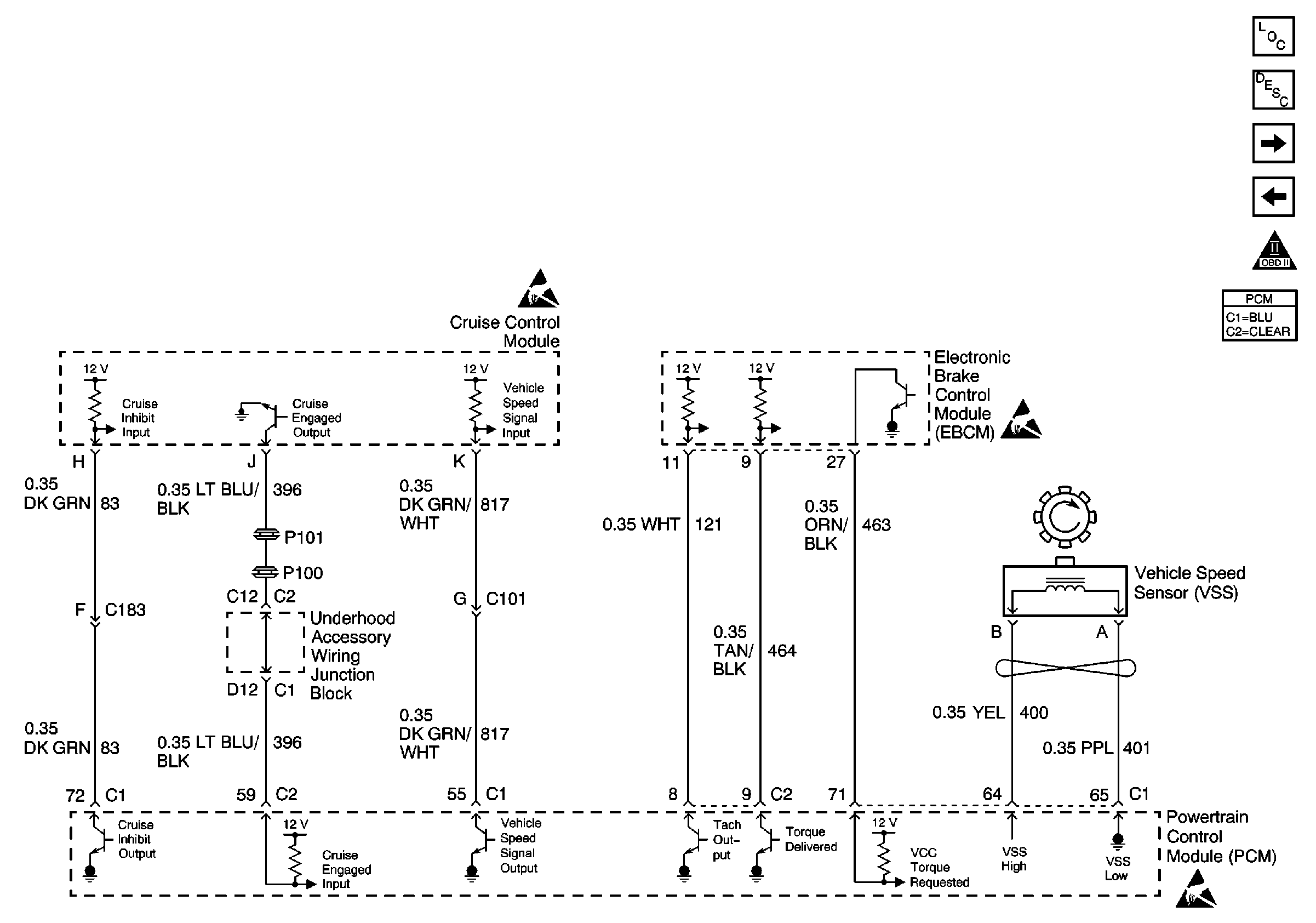
Refer to Engine Control Schematic
Cruise Control Module, EBCM and VSS

.
Circuit Description
The electronic brake traction control module (EBTCM) pulls the traction control Delivered Torque circuit up to approximately 12 volts. The powertrain control module (PCM) pulse width modulates (PWM) the circuit to ground, creating a signal that represents the percentage of engine torque output. The EBTCM uses this PWM signal for the traction control. The PCM provides the ground via an internal solid state device called a driver. The primary function of the driver is to supply the ground for the component being controlled. Each driver has a fault line which is monitored by the PCM. If the fault detection circuit senses a voltage other than what is expected, this DTC will set.
Conditions for Running the DTC
| • | The brakes are not applied. |
| • | The PCM is in the Closed Loop fuel mode. |
Conditions for Setting the DTC
| • | The PCM detects an incorrect voltage on the traction control Delivered Torque circuit. |
| • | The condition is present for 2.5 seconds. |
Action Taken When the DTC Sets
| • | The powertrain control module (PCM) stores the DTC information into memory when the diagnostic runs and fails. |
| • | The malfunction indicator lamp (MIL) will not illuminate. |
| • | The PCM records the operating conditions at the time the diagnostic fails. The PCM stores this information in the Failure Records. |
Conditions for Clearing the MIL/DTC
| • | A History DTC will clear after 40 consecutive warm-up cycles, if no failures are reported by this or any other non-emission related diagnostic. |
| • | The current DTC will clear when the diagnostic runs and does not fail. |
| • | Use a scan tool in order to clear the MIL diagnostic trouble code. |
| • | Interrupting the PCM battery voltage may or may not clear DTCs. This practice is not recommended. Refer to Powertrain Control Module Description , Clearing Diagnostic Trouble Codes. |
Diagnostic Aids
Notice: Use the connector test adapter kit J 35616-A for any test that
requires probing the following items:
• The PCM harness connectors • The electrical center fuse/relay cavities • The component terminals • The component harness connector
Check for an intermittent poor connection at both the PCM and the EBTCM.
If the problem is intermittent, refer to Intermittent Conditions .
Test Description
The number below refers to the step numbers on the diagnostic table.
Step | Action | Value(s) | Yes | No | ||||||
|---|---|---|---|---|---|---|---|---|---|---|
1 | Did you perform the Powertrain On-Board Diagnostic (OBD) System Check? | -- | ||||||||
2 |
Does the display indicate OK continuously? | -- | Go to Diagnostic Aids | |||||||
3 |
Is the voltage equal to or more than the specified value? | 10.0 V | ||||||||
4 |
Was a problem found and corrected? | -- | ||||||||
5 | Check for poor connections and terminal tension at the PCM. Refer to Testing for Intermittent Conditions and Poor Connections in Wiring Systems. Was a problem found and corrected? | -- | ||||||||
6 | Check for poor connections and terminal tension at the EBTCM. Refer to Testing for Intermittent Conditions and Poor Connections . Was a problem found and corrected? | -- | Go to Diagnostic Starting Point in Antilock Brake System | |||||||
7 |
Important:: The replacement PCM must be programmed. Replace the PCM. Refer to Powertrain Control Module Replacement/Programming . Is the action complete? | -- | -- | |||||||
8 |
Does the scan tool indicate that this test ran and passed? | -- | ||||||||
9 | Review the captured data using the scan tool. Are there any DTCs set that have not been diagnosed? | -- | Go to the applicable DTC table | System OK |
