Bank 1 AIR Control Valve
Removal Procedure
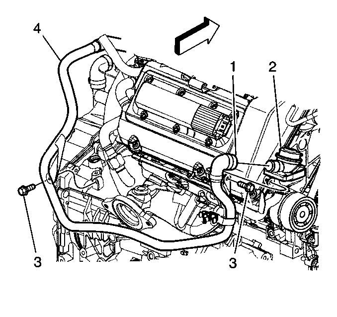
- Remove the 2 mounting nuts retaining the coolant recovery tank.
- Move the tank out of the way leaving the hose connected.
- Remove the drive belt and tensioner. Refer to Drive Belt Tensioner Replacement in Engine Mechanical.
- Disconnect the vacuum line from the actuator diaphragm (2).
- Raise the vehicle.
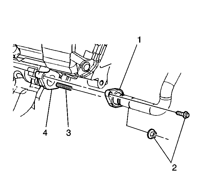
- Remove the mounting bolt and the nut (2) that attach the discharge tube flange (1) of the AIR control valve to the AIR manifold (4).
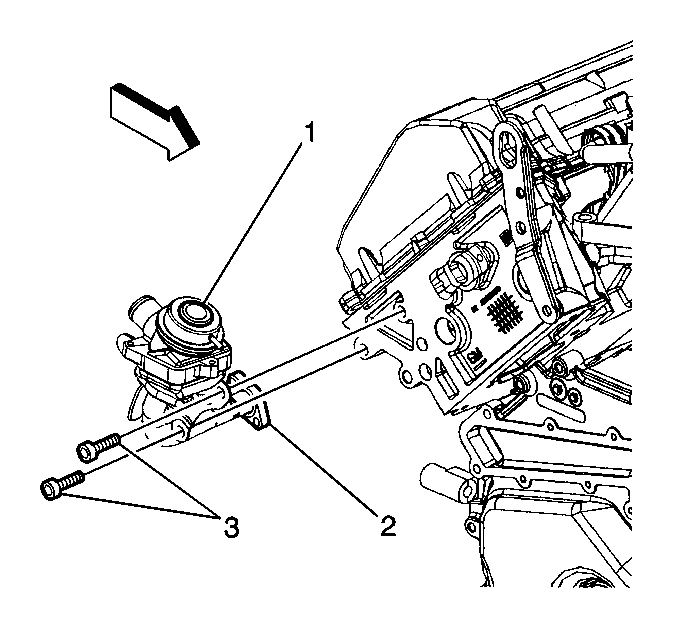
- Remove the mounting bolts (3) that attach the AIR control valve bracket to the cylinder head.
- Remove the AIR control valve assembly (1) from the cylinder head and from the AIR system Y-pipe.
Caution: To avoid any vehicle damage, serious personal injury or death when major components are removed from the vehicle and the vehicle is supported by a hoist, support the vehicle with jack stands at the opposite end from which the components are being removed and strap the vehicle to the hoist.
Installation Procedure
- Install the AIR control valve assembly (2) onto the AIR system Y-pipe (4).
- Attach the discharge tube flange (1) of the AIR control valve to the AIR manifold (4) and hand tighten the mounting bolt and the nut (2).
- Install the mounting bracket to the cylinder head and hand tighten the mounting bolts (3).
- Lower the vehicle.
- Connect the vacuum line to the actuator diaphragm (1).
- Install the drive belt and tensioner. Refer to Drive Belt Tensioner Replacement in Engine Mechanical.
- Move the coolant recovery tank back into position.
- Install the 2 mounting nuts to retain the coolant recovery tank .


Notice: Use the correct fastener in the correct location. Replacement fasteners must be the correct part number for that application. Fasteners requiring replacement or fasteners requiring the use of thread locking compound or sealant are identified in the service procedure. Do not use paints, lubricants, or corrosion inhibitors on fasteners or fastener joint surfaces unless specified. These coatings affect fastener torque and joint clamping force and may damage the fastener. Use the correct tightening sequence and specifications when installing fasteners in order to avoid damage to parts and systems.

Tighten
Tighten the mounting bolts for the discharge tube flange to 9 N·m
(80 lb in).
Tighten
Tighten the bracket mounting bolts to 25 N·m (18 lb ft).
Tighten
Tighten the mounting nuts to 1 N·m (9 lb in)
Bank 2 AIR Control Valve
Removal Procedure
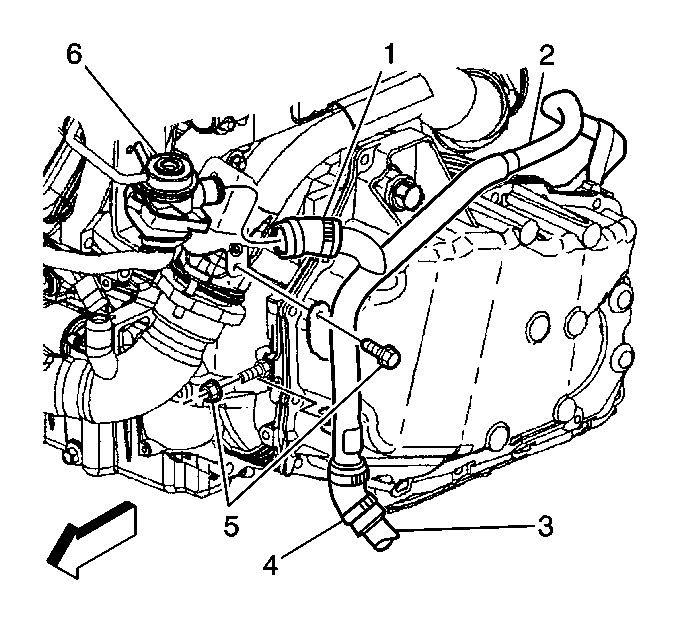
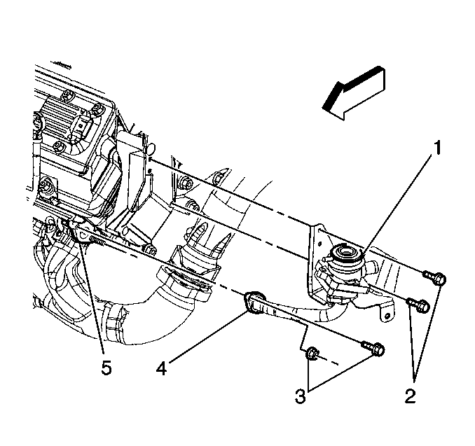
- Disconnect the vacuum line from the actuator diaphragm (6).
- Remove the mounting bolt and the nut (3) that attach the discharge tube flange (4) of the AIR control valve to the AIR manifold (5).
- Remove the mounting bolts (2) that attach the mounting bracket of the AIR control valve to the engine lift bracket.
- Remove the AIR control valve assembly from the cylinder head and from the AIR system Y-pipe.
Installation Procedure
- Install the AIR control valve assembly (6) onto the AIR system Y-pipe (1).
- Attach the discharge tube flange (4) to the AIR manifold (5) and hand tighten the mounting bolt and the nut (3).
- Install the mounting bracket for the AIR control valve assembly to the engine lift bracket and hand tighten the mounting bolts (2).
- Connect the vacuum line to the actuator diaphragm (1).


Notice: Use the correct fastener in the correct location. Replacement fasteners must be the correct part number for that application. Fasteners requiring replacement or fasteners requiring the use of thread locking compound or sealant are identified in the service procedure. Do not use paints, lubricants, or corrosion inhibitors on fasteners or fastener joint surfaces unless specified. These coatings affect fastener torque and joint clamping force and may damage the fastener. Use the correct tightening sequence and specifications when installing fasteners in order to avoid damage to parts and systems.
Tighten
Tighten the mounting bolts for the discharge tube flange to 9 N·m
(80 lb in).
Tighten
Tighten the assembly bracket mounting bolts to 25 N·m (18 lb ft).
AIR Solenoid Valve
Removal Procedure
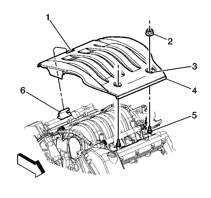
- Remove the mounting nuts (2) from the fuel injector sight shield .
- Lift the injector sight shield off the mounting studs by lifting at the front (4) of the cover.
- Disconnect the electrical connector at the solenoid.
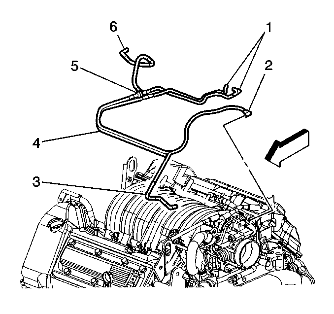
- Disconnect the vacuum lines (1) from the solenoid.
- Remove the mounting bolts from the AIR solenoid valve assembly .
- Remove the AIR solenoid valve assembly.
Installation Procedure
- Place the AIR solenoid valve assembly in position.
- Install the mounting bolts to the AIR solenoid valve assembly .
- Connect the vacuum lines (1) to the solenoid.
- Connect the electrical connector to the solenoid.
- Keeping the injector sight shield as level as possible, place the rear (1) of the shield under the mounting bracket (6).
- Align and press the injector sight shield (4) onto the mounting studs (5).
- Install the mounting nuts (2) onto the mounting studs (5).


Notice: Use the correct fastener in the correct location. Replacement fasteners must be the correct part number for that application. Fasteners requiring replacement or fasteners requiring the use of thread locking compound or sealant are identified in the service procedure. Do not use paints, lubricants, or corrosion inhibitors on fasteners or fastener joint surfaces unless specified. These coatings affect fastener torque and joint clamping force and may damage the fastener. Use the correct tightening sequence and specifications when installing fasteners in order to avoid damage to parts and systems.
Tighten
Tighten the mounting nuts to 3 N·m (27 lb in).
AIR Pump Exhaust Pipe
Removal Procedure
- Remove the retaining screws from the front portion of the left front wheel well splash shield.
- Lower the splash shield far enough to gain access to the AIR pump assembly.
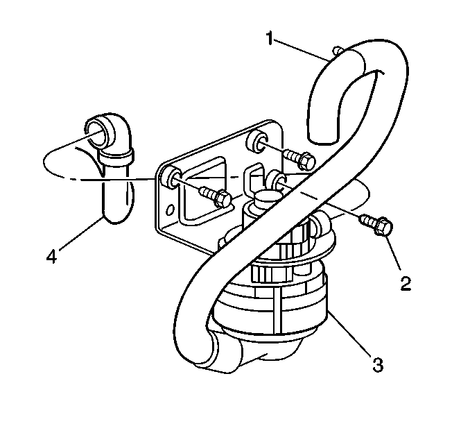
- Loosen and lower the pinch clamp from the AIR exhaust pipe hose (4) .
- Disconnect the AIR exhaust pipe (4) from the AIR pump (3).
- Loosen and lower the pinch clamp (4) from the AIR pump exhaust hose at the AIR system Y-pipe (2).
- Disconnect the AIR pump exhaust pipe (3) from the AIR system Y-pipe (2).
- Remove the AIR pump exhaust pipe (3).

Installation Procedure
- Position the AIR pump exhaust pipe between the AIR pump and the AIR system Y-pipe.
- Connect the AIR pump exhaust pipe (3) to the AIR system Y-pipe (2).
- Place the pinch clamp (4) around the connection for the AIR pump exhaust hose at the AIR system Y-pipe inlet port.
- Attach the AIR exhaust pipe (4) to the AIR pump outlet port.
- Place the pinch clamp around the AIR pump outlet port and exhaust hose connection.
- Raise the wheel well splash shield into position.
- Re-install the screws retaining the wheel well splash shield.


AIR System Y-Pipe
Removal Procedure
- The engine/transaxle/frame assembly must be lowered from the vehicle in order to remove the AIR System Y pipe. The engine and transaxle do not need to be separated. Refer to Engine Replacement in Engine Mechanical.
- Loosen and lower the pinch clamp (4) from the AIR pump exhaust pipe .
- Disconnect the AIR pump exhaust pipe (3) from the AIR system Y-pipe (2).
- Remove the front mounting bolts (5) from the AIR system Y-pipe .
- Disconnect the AIR pump exhaust pipe (1) from the AIR control valve (6).
- Remove the rear mounting bolts (3) from the AIR system Y-pipe .
- Disconnect the AIR pump exhaust pipe (4) from the AIR control valve (2).
- Remove the AIR system Y-pipe.


Installation Procedure
- Position the AIR system Y-pipe between the AIR control valves.
- At the rear of the engine, connect the AIR System Y-pipe (1) to the Bank 1 AIR control valve.
- Install the rear AIR System Y-pipe mounting bolts (3).
- At the front of the engine, connect the AIR system Y-pipe (2) to the Bank 2 AIR control valve (6).
- Install the front mounting bolts (5) to the AIR system Y-pipe .
- Connect the AIR pump exhaust pipe (3) to the AIR system Y-pipe (2).
- Reposition the pinch clamp (4) on the AIR pump exhaust hose at the Y-pipe inlet port.
- Install the engine/transaxle/frame assembly. Refer to Engine Replacement in Engine Mechanical.

Notice: Use the correct fastener in the correct location. Replacement fasteners must be the correct part number for that application. Fasteners requiring replacement or fasteners requiring the use of thread locking compound or sealant are identified in the service procedure. Do not use paints, lubricants, or corrosion inhibitors on fasteners or fastener joint surfaces unless specified. These coatings affect fastener torque and joint clamping force and may damage the fastener. Use the correct tightening sequence and specifications when installing fasteners in order to avoid damage to parts and systems.
Tighten
Tighten the mounting bolts to 9 N·m (80 lb in).

Tighten
Tighten the mounting bolts to 9 N·m (80 lb in).
Bank 1 AIR Manifold
Removal Procedure
- Loosen the bolts that retain the AIR control valve bracket to the cylinder head.
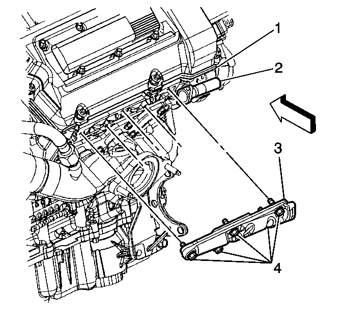
- Remove the mounting bolt and the nut (2) that attach the discharge tube flange (1) of the AIR control valve to the AIR manifold (4).
- Remove the mounting bolts (4) that attach the AIR manifold (3) to the cylinder head (1).
- Separate the discharge tube flange (2) of the AIR control valve from the AIR manifold (3).
- Remove the AIR manifold (3).

Installation Procedure
- Install the AIR manifold (3) to the cylinder head (1).
- Install the discharge tube flange (1) to the AIR manifold (4).

Notice: Use the correct fastener in the correct location. Replacement fasteners must be the correct part number for that application. Fasteners requiring replacement or fasteners requiring the use of thread locking compound or sealant are identified in the service procedure. Do not use paints, lubricants, or corrosion inhibitors on fasteners or fastener joint surfaces unless specified. These coatings affect fastener torque and joint clamping force and may damage the fastener. Use the correct tightening sequence and specifications when installing fasteners in order to avoid damage to parts and systems.
Tighten
Tighten the mounting bolts (4) to 10 N·m (89 lb in).

Tighten
Tighten the mounting bolt and nut (2) to 9 N·m (80 lb in).
Tighten
Tighten the assembly bracket mounting bolts to 25 N·m (18 lb ft).
Bank 2 AIR Manifold
Removal Procedure
- Remove the engine coolant fans. Refer to Engine Cooling Fan Replacement in Engine Cooling.
- Remove the oil level indicator tube. Refer to Oil Level Indicator and Tube Replacement in Engine Mechanical.
- Loosen the bolts retaining the AIR control valve bracket to the cylinder head .
- Remove the mounting bolt and the nut (2) that attach the discharge tube flange (1) of the AIR control valve to the AIR manifold (4).
- Remove the mounting bolts (4) that attach the AIR manifold (3) to the cylinder head (1).
- Separate the discharge tube flange (2) from the AIR manifold (3).
- Remove the AIR manifold (3).


Installation Procedure
- Install the AIR manifold (3) to the cylinder head (1).
- Install the discharge tube flange (1) to the AIR manifold (4).
- Install the oil level indicator tube. Refer to Oil Level Indicator and Tube Replacement in Engine Mechanical.
- Install the engine coolant fans. Refer to Engine Cooling Fan Replacement in Engine Cooling.

Notice: Use the correct fastener in the correct location. Replacement fasteners must be the correct part number for that application. Fasteners requiring replacement or fasteners requiring the use of thread locking compound or sealant are identified in the service procedure. Do not use paints, lubricants, or corrosion inhibitors on fasteners or fastener joint surfaces unless specified. These coatings affect fastener torque and joint clamping force and may damage the fastener. Use the correct tightening sequence and specifications when installing fasteners in order to avoid damage to parts and systems.
Tighten
Tighten the mounting bolts to 10 N·m (89 lb in).

Tighten
Tighten the bolt and nut to 9 N·m (80 lb in).
Tighten
Tighten the bracket mounting bolts to 25N·m (18 lb ft).
