Tools Required
| • | J 42038 Camshaft Holding Fixture |
| • | J 43032 Crankshaft Rotation Socket |
Removal Procedure
- Remove the camshaft covers. Refer to Camshaft Cover Replacement .
- Install the J 42038 to the camshafts on the left (front) and right (rear) cylinder heads.
- Remove the engine front cover. Refer to Engine Front Cover Replacement .
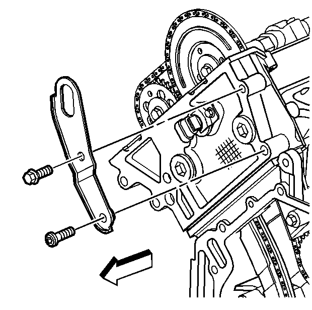
- Remove the front engine lift bracket retaining bolts.
- Remove the front engine lift bracket.
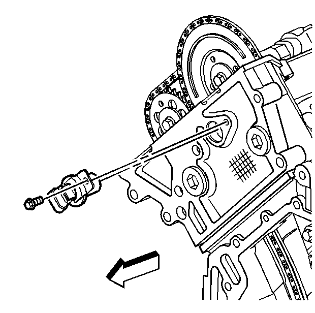
- Remove the camshaft position sensor retaining bolt.
- Remove the camshaft position sensor (1). Refer to Crankshaft Position Sensor Replacement in Engine Controls - 3.5L.
- Remove the right cylinder head exhaust camshaft sprocket bolt to allow clearance for the right cylinder head chain guide.
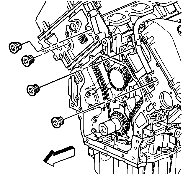
- Remove the four chain guide access plugs located in the cylinder heads. Note the O-ring seal on each access plug.
- Loosen both primary timing chain tensioner bolts.
- Remove the lower primary timing chain tensioner bolt allowing the tensioner to swing downward and expand. This will release tension on the primary drive chain.
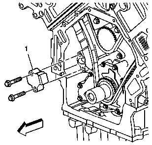
- Remove the upper tensioner bolt.
- Remove the primary drive chain tensioner (1).
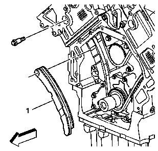
- Remove the primary timing chain tensioner shoe retaining bolt.
- Remove the primary timing chain tensioner shoe (1) by pushing the guide downward slightly and then pulling it up through the cylinder head.
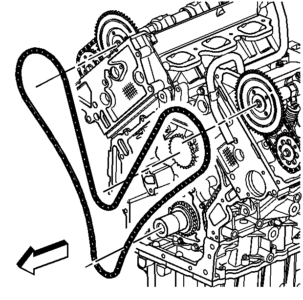
- Remove the primary timing chain from the RH camshaft sprocket and allow the chain to fall into the oil pump area of the cylinder block.
- Remove the primary timing chain.
Installation Procedure
- Install the primary timing chain.
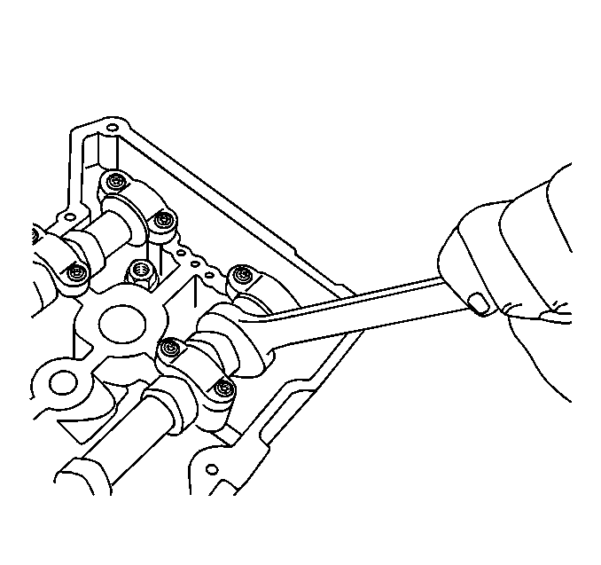
- To assist in timing chain installation, use an open end wrench on the hex cast into the camshaft to provide minor adjustments to the secondary sprocket position.
- When installing the primary timing chain you must set the base engine timing. Base engine timing is set with cylinder number one at top dead center (TDC) starting the intake stroke and with the correct camshaft to balance shaft to crankshaft relationship. To set the correct base engine timing proceed as follows:
- Ensure the darkened timing links on the timing chain are facing toward the front of the engine.
- Center the timing mark (1) on the left hand intake camshaft between the paired darkened timing links (2) and wrap the chain around the sprocket. Allow the remainder of the chain to drop into the crankcase area once the timing mark is aligned.
- Fabricate a hook out of wire and feed it down through the right cylinder head. Use the hook to pull the remainder of the timing chain up to the right intake camshaft sprocket.
- While pulling the timing chain up to the right cylinder head, align the marked timing chain links with the balance shaft (7) and crankshaft (6) sprockets.
- Wrap the timing chain around the right intake camshaft sprocket and align the marked linked (8) with the sprocket's timing mark (9).
- Make sure all the timing marks are properly aligned with the marked timing chain links.
- Install the primary timing chain tensioner shoe (1).
- Install the primary timing chain tensioner shoe retaining bolt using the access hole in the cylinder head.
- Collapse the primary timing chain tensioner using the following procedure:
- As the ratchet lever moves to its first click, hold the tensioner shoe inward. Insert a pin through the hole in the release lever.
- The locked ratchet mechanism should hold the shoe in a collapsed position.
- Install the primary timing chain tensioner (1) and the retaining bolts.
- Ensure all the timing marks (1-9) are properly aligned. Make adjustments as necessary.
- Remove the pin holding the tensioner to tighten any slack in the timing chain.
- Install the four chain guide access plugs.
- Install the front engine lift bracket hex head and the internal drive retaining bolts.
- Install the camshaft position sensor and retaining bolt. Refer to Crankshaft Position Sensor Replacement in Engine Controls - 3.5L.
- Remove the J 42038 from the camshafts on the left (front) and right (rear) cylinder heads.
- Verify correct timing chain and timing mark alignments.
- Install the camshaft covers. Refer to Camshaft Cover Replacement .
- Install the engine front cover. Refer to Engine Front Cover Replacement .

Important: Do not remove the J 42038 .
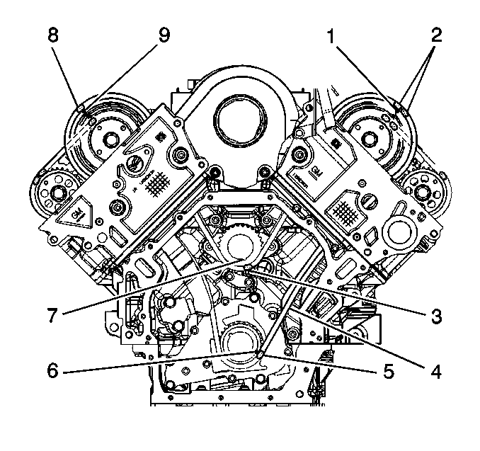
| 3.1. | Rotate the crankshaft until cylinder number one is at top dead center and the crankshaft sprocket timing mark (6) is at the four o'clock position. |
| 3.2. | Rotate the balance shaft until its timing mark (7) is at the five o'clock position. |

Notice: Use the correct fastener in the correct location. Replacement fasteners must be the correct part number for that application. Fasteners requiring replacement or fasteners requiring the use of thread locking compound or sealant are identified in the service procedure. Do not use paints, lubricants, or corrosion inhibitors on fasteners or fastener joint surfaces unless specified. These coatings affect fastener torque and joint clamping force and may damage the fastener. Use the correct tightening sequence and specifications when installing fasteners in order to avoid damage to parts and systems.
Tighten
Tighten the primary timing chain tensioner shoe bolt to 30 N·m
(22 lb ft).
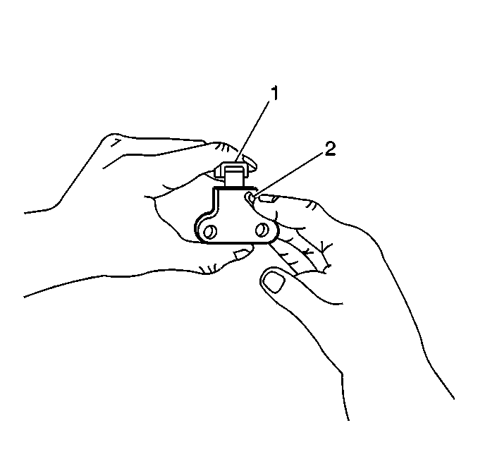
| 12.1. | Rotate the ratchet release lever (2) counterclockwise and hold. |
| 12.2. | Collapse the tensioner shoe (1) and hold. |
| 12.3. | Release the ratchet lever and slowly release the pressure on the shoe. |

Important: Ensure the tensioner release lever faces toward you before tightening.
Tighten
Tighten the primary timing chain tensioner bolts to 25 N·m
(18 lb ft).


Important: Ensure each chain guide access plug has an O-ring installed.
Tighten
Tighten the chain guide access plugs to 5 N·m (44 lb in).

Tighten
| • | Tighten the front lift bracket hex head bolt to 50 N·m (37 lb ft). |
| • | Tighten the front lift bracket internal drive bolt to 25 N·m (18 lb ft). |

Tighten
Tighten the camshaft position sensor retaining bolt to 9 N·m
(80 lb in).
