Removal Procedure
Tools Required
J 38185 Hose Clamp Pliers
Caution: With a pressurized cooling system, the coolant temperature in the radiator can be considerably higher than the boiling point of the solution at atmospheric pressure. Removal of the surge tank cap, while the cooling system is hot and under high pressure, causes the solution to boil instantaneously with explosive force. This will cause the solution to spew out over the engine, the fenders, and the person removing the cap. Serious bodily injury may result.
- Disconnect the battery ground (negative) cable. Refer to Battery Negative Cable Disconnection and Connection in Engine Electrical.
- Partially drain the cooling system. Refer to Cooling System Draining and Filling .
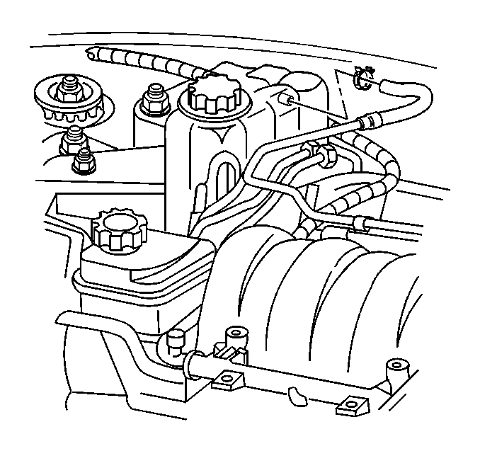
- Remove the inlet surge tank hose clamp.
- Disconnect the inlet surge tank hose.
- Remove the outlet surge tank hose clamp.
- Disconnect the outlet surge tank hose.
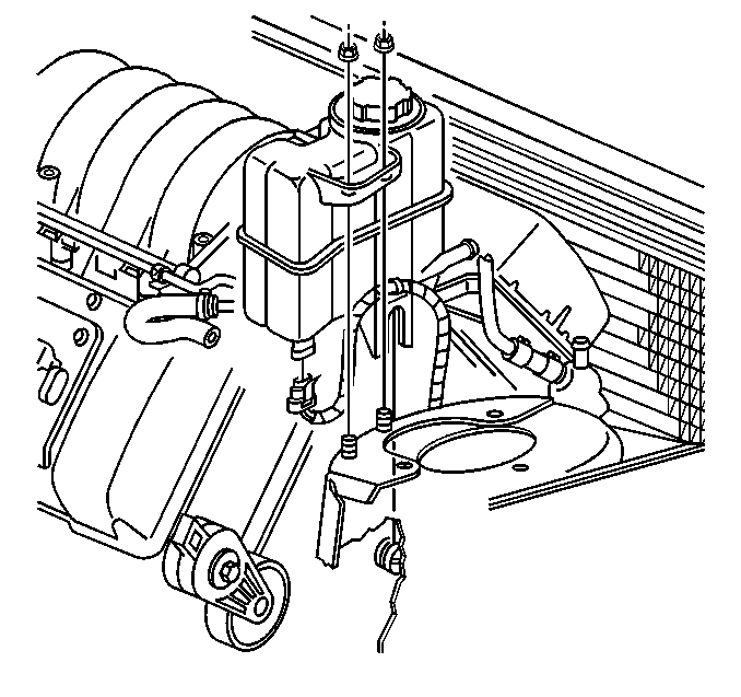
- Remove the surge tank nuts.
- Raise the surge tank.
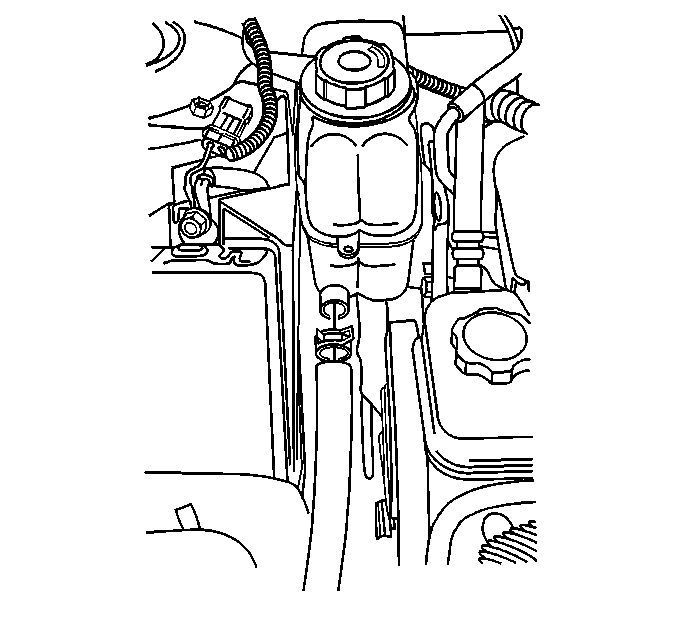
- Disconnect the wiring harness connector from the coolant level sensor.
- Remove the surge tank.
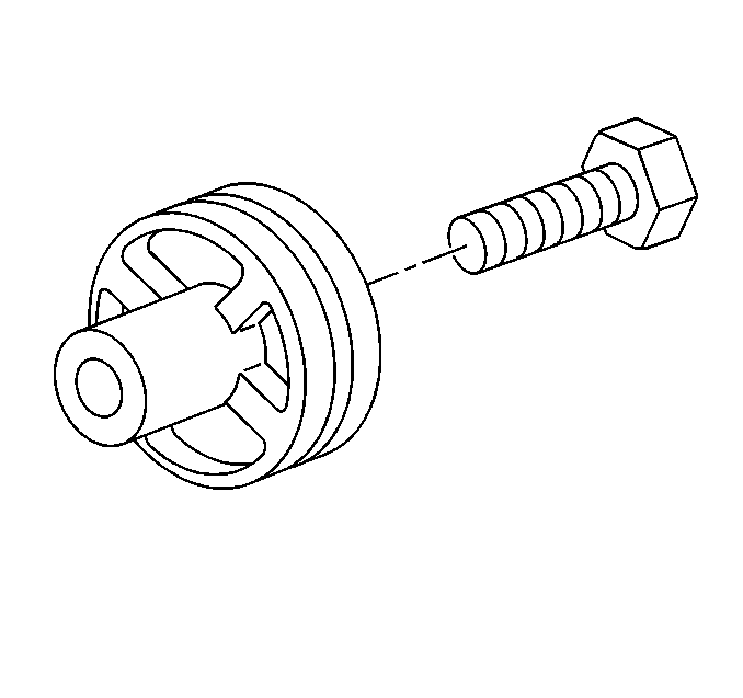
- Inspect the surge tank retainer mounted to the shock tower stud, replace if necessary.
- If replacing the surge tank, remove the coolant level sensor.


Installation Procedure
Tools Required
J 38185 Hose Clamp Pliers
- If removed, install the surge tank retainer.
- If removed, install the coolant level sensor into the surge tank.
- Connect the wiring harness connector to the coolant level sensor.
- Install the surge tank.
- Install the surge tank nuts.
- Connect the outlet hose to the surge tank.
- Install the outlet surge tank hose clamp.
- Connect the inlet hose to the surge tank.
- Install the inlet surge tank hose clamp.
- Fill the cooling system. Refer to Cooling System Draining and Filling in Engine Electrical.
- Connect the battery ground (negative) cable. Refer to Battery Negative Cable Disconnection and Connection in Engine Electrical.
- Inspect for leaks.


Notice: Use the correct fastener in the correct location. Replacement fasteners must be the correct part number for that application. Fasteners requiring replacement or fasteners requiring the use of thread locking compound or sealant are identified in the service procedure. Do not use paints, lubricants, or corrosion inhibitors on fasteners or fastener joint surfaces unless specified. These coatings affect fastener torque and joint clamping force and may damage the fastener. Use the correct tightening sequence and specifications when installing fasteners in order to avoid damage to parts and systems.
Tighten
Tighten the surge tank nuts to 3 N·m (30 lb in).


