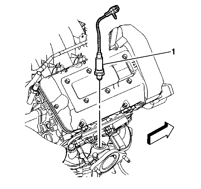
Removal Procedure
Sensor 1
- Disconnect the HO2S electrical connector.
- Remove the electrical connector from the mounting hole.
- Remove the HO2S from the exhaust manifold.
Notice: Remove oxygen sensors with the engine temperature above 48°C (120°F). Otherwise the oxygen sensors may be difficult to remove.
Notice: Handle the oxygen sensors carefully in order to prevent damage to the component. Keep the electrical connector and the exhaust inlet end free of contaminants. Do not use cleaning solvents on the sensor. Do not drop or mishandle the sensor.
Important: A special anti-seize compound is used on the oxygen sensor threads. New service sensors should already have the compound applied to the threads. Coat the threads of a reused sensor with anti-seize compound GM PN 12377953 or equivalent.
If a sensor is reused, install a new gasket GM PN 01555476 or equivalent .
Installation Procedure
Sensor 1
- Install the HO2S in the rear exhaust manifold.
- Install the electrical connector into the mounting hole.
- Connect the HO2S electrical connector.

Notice: Use the correct fastener in the correct location. Replacement fasteners must be the correct part number for that application. Fasteners requiring replacement or fasteners requiring the use of thread locking compound or sealant are identified in the service procedure. Do not use paints, lubricants, or corrosion inhibitors on fasteners or fastener joint surfaces unless specified. These coatings affect fastener torque and joint clamping force and may damage the fastener. Use the correct tightening sequence and specifications when installing fasteners in order to avoid damage to parts and systems.
Important: Ensure that the correct replacement HO2S is used. The HO2S 1 (engine) and the HO2S 2 (post-converter) are both 6.6 watt Denso sensors. Due to differences in pigtail length, the sensors use different connectors and are not interchangeable.
Tighten
Tighten the HO2S to 41 N·m (30 lb ft).
Removal Procedure
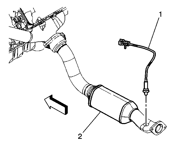
Sensor 2 (Post-Converter)
- Raise the vehicle.
- Disconnect the HO2S electrical connector.
- Remove the electrical connector from the mounting hole.
- Remove the HO2S from the exhaust pipe.

Caution: To avoid any vehicle damage, serious personal injury or death when major components are removed from the vehicle and the vehicle is supported by a hoist, support the vehicle with jack stands at the opposite end from which the components are being removed and strap the vehicle to the hoist.
Installation Procedure
Sensor 2 (Post-Converter)
- Install the HO2S in the rear exhaust pipe.
- Install the electrical connector into the mounting hole.
- Connect the HO2S electrical connector.
- Lower the vehicle.

Notice: Use the correct fastener in the correct location. Replacement fasteners must be the correct part number for that application. Fasteners requiring replacement or fasteners requiring the use of thread locking compound or sealant are identified in the service procedure. Do not use paints, lubricants, or corrosion inhibitors on fasteners or fastener joint surfaces unless specified. These coatings affect fastener torque and joint clamping force and may damage the fastener. Use the correct tightening sequence and specifications when installing fasteners in order to avoid damage to parts and systems.
Important: Ensure that the correct replacement HO2S is used. The HO2S 1 (engine) and the HO2S 2 (post-converter) are both 6.6 watt Denso sensors. Due to differences in pigtail length, the sensors use different connectors and are not interchangeable.
Tighten
Tighten the HO2S to 41 N·m (30 lb ft).
