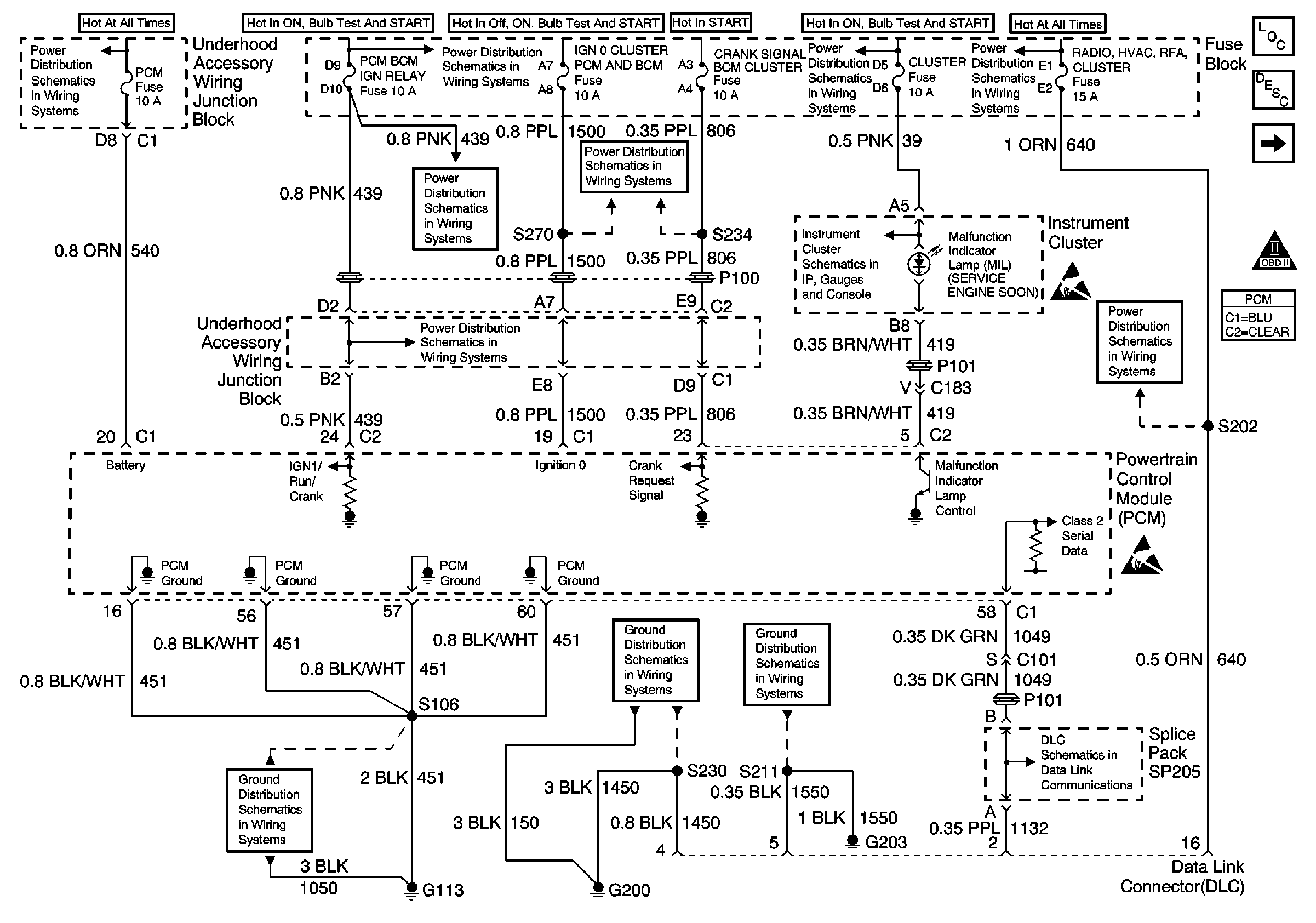
Refer to Engine Controls Schematic
PCM Power and Grounds

Circuit Description
The PCM controlled starter system consists of the following components:
| • | The ignition switch |
| • | The Crank Request Signal circuit |
| • | The PCM |
| • | The Starter Enable (Crank) relay |
| • | The Transaxle Range switch |
| • | The starter solenoid |
When the ignition switch is turned to the Start position, B+ is sent to the powertrain control module (PCM) via the Crank Request Signal circuit. The PCM has the ability to disallow starter operation if conditions inappropriate for starter operation exist. The PCM will disable the starter under the following conditions:
| • | The engine is running |
| • | A correct vehicle theft deterrent (VTD) password is not received from the body control module (BCM) |
| • | The vehicle operator continues to engage the starter for an extended period of time |
If no inhibiting conditions are present, and the PCM detects voltage on the Crank Request Signal circuit, the PCM grounds the Starter Enable (Crank) relay control circuit. The Transaxle Range switch must be in Park or Neutral for the control circuit to operate the relay. Current from the crank maxifuse flows through the relay to the starter solenoid.
Diagnostic Aids
This diagnostic procedure is intended to identify electrical malfunctions within the PCM controlled portion of the starting system. For additional system diagnosis, refer to Diagnostic Starting Point in Wiring Systems.
Use the J 35616 connector test adapter kit for any test that requires probing the PCM harness connectors, electrical center fuse/relay cavities, component terminals or a component harness connector. Using this kit will prevent damage caused by improper probing of connector terminals.
If the problem is intermittent, refer to Intermittent Conditions for diagnosis.
Test Description
The number below refers to the step number on the diagnostic table.
Step | Action | Value(s) | Yes | No | ||||||||
|---|---|---|---|---|---|---|---|---|---|---|---|---|
1 | Did you perform the PCM Controlled Starter Diagnosis? | -- | Go to Powertrain Control Module Controlled Starter Diagnosis | |||||||||
Monitor the Crank Request using a scan tool. Does the scan tool indicate No with the key in the On position, and Yes with the key in the Start position? | -- | Go to Diagnostic Aids | ||||||||||
3 | Does the scan tool always indicate the Crank Request is No? | -- | ||||||||||
4 | Check the Crank Signal fuse. Is the fuse OK? | -- | ||||||||||
5 |
Is the voltage near the specified value with the key in the Start position? | B+ | ||||||||||
6 |
Is the voltage near the specified value with the key in the Start position? | B+ | ||||||||||
7 | Check for the following conditions and repair as necessary:
Refer to Testing for Intermittent Conditions and Poor Connections in Wiring Systems . Is the action complete? | -- | -- | |||||||||
8 |
Is the voltage near the specified value with the key in the On position? | B+ | ||||||||||
9 |
Is voltage indicated? | -- | ||||||||||
10 | Check for continuity between the Crank Request Signal circuit and the following circuits in the ignition switch harness connector:
Is continuity indicated? | -- | ||||||||||
11 | Repair the open or high resistance in the Crank Request Signal circuit. Refer to Wiring Repairs in Wiring Systems. Is the action complete? | -- | -- | |||||||||
12 | Check for the following conditions and repair as necessary:
Is the action complete? | -- | -- | |||||||||
13 | Repair a short to power in the Crank Request Signal circuit . Refer to Wiring Repairs in Wiring Systems. Is the action complete? | -- | -- | |||||||||
14 | Repair the circuits that are shorted together. Refer to Wiring Repairs in Wiring Systems. Is the action complete? | -- | -- | |||||||||
15 | Check for poor connections or terminal tension at the ignition switch. Refer to Testing for Intermittent Conditions and Poor Connections in Wiring Systems Was a problem found and corrected? | -- | ||||||||||
16 | Replace the ignition switch. Is the action complete? | -- | -- | |||||||||
17 | Check for poor connections or terminal tension at the PCM. Refer to Testing for Intermittent Conditions and Poor Connections in Wiring Systems. Was a problem found and corrected? | -- | ||||||||||
18 |
Important: The replacement PCM must be programmed. Replace the PCM. Refer to Powertrain Control Module Replacement/Programming Is the action complete? | -- | -- | |||||||||
19 | Monitor Crank Request using a scan tool. Does the scan tool indicate No with the key in the On position, and Yes with the key in the Start position? | -- | System OK |
