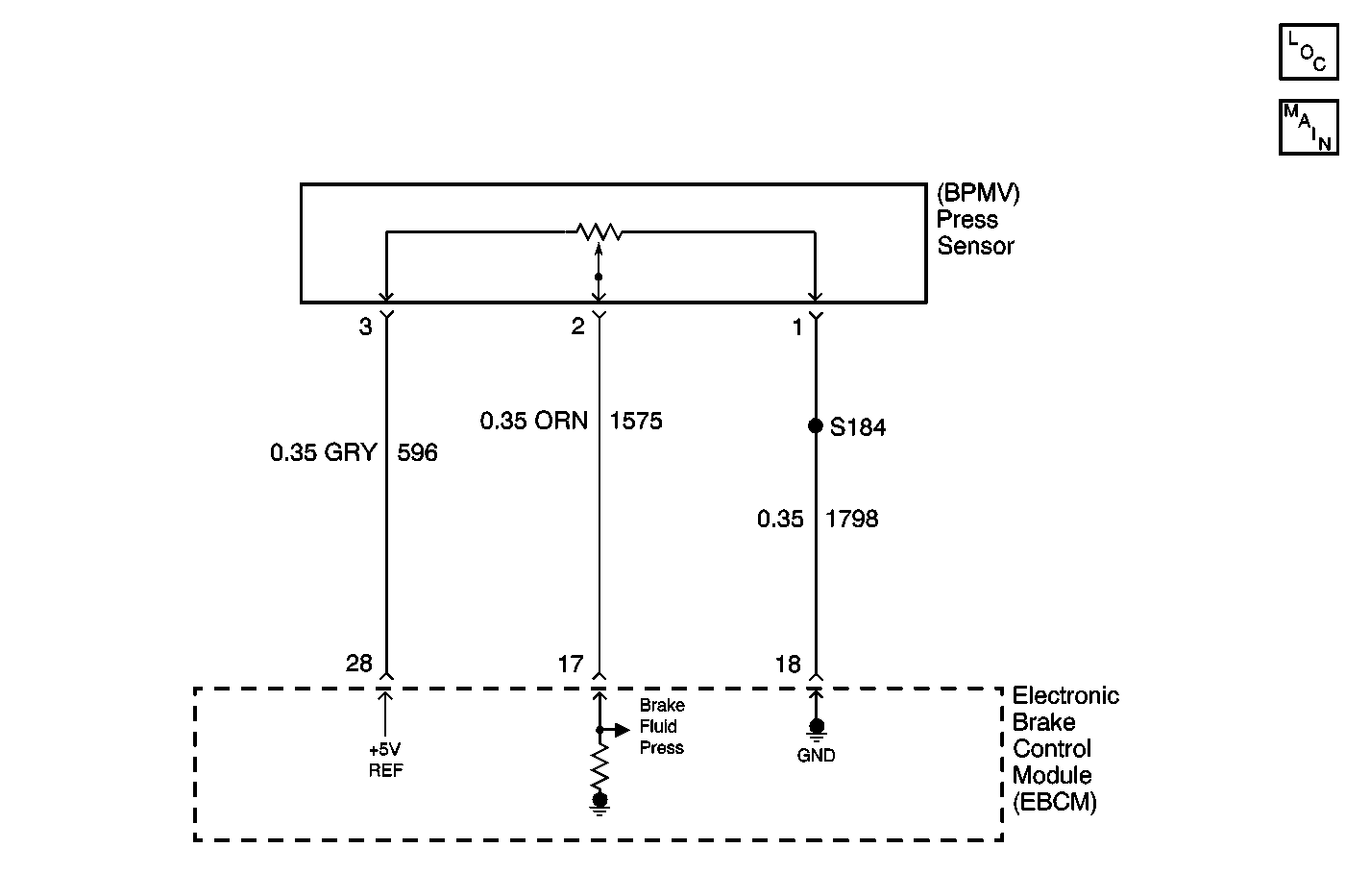
Circuit Description
The brake pressure sensor reference voltage is monitored for an over or under voltage condition.
Conditions for Running the DTC
| • | The ignition is ON. |
| • | The vehicle speed is greater than 40 km/h (25 mph). |
Conditions for Setting the DTC
A malfunction is detected if the supply voltage is above 5.6 volts or below 4.4 volts for more than 60 milliseconds.
Action Taken When the DTC Sets
| • | A malfunction DTC is set |
| • | ABS, TCS and VSES are disabled |
| • | ABS, TCS, SERVICE VEHICLE SOON and PCS lamp indicators are ON |
Conditions for Clearing the DTC
| • | The condition for the DTC is no longer present. |
| • | A history DTC will clear after 124 consecutive ignition cycles if the condition for the malfunction is no longer present. |
| • | Using a scan tool. |
| • | The EBCM automatically clears the history DTC when a current DTC is not detected in 124 consecutive drive cycles. |
Diagnostic Aids
Possible causes of this DTC are the following conditions:
| • | An open in the pressure sensor supply voltage circuit |
| • | A short to ground in the pressure sensor supply voltage circuit |
| • | A short to B+ in the pressure sensor supply voltage circuit |
Test Description
The number(s) below refer to the step number(s) on the diagnostic table.
-
Tests for specified voltage on the brake pressure signal circuit.
-
Checks to see if the brake pressure signal circuit voltage was below specified voltage.
-
Checks to see if the brake pressure signal circuit voltage was above specified voltage.
-
Tests for a short to ground in the 5 volt reference circuit of the brake pressure sensor.
-
Tests for a short to voltage in the 5 volt reference circuit of the brake pressure sensor.
-
Tests for a high resistance or an open in the ground circuit of the brake pressure sensor.
-
Checks the brake pressure sensor connector for poor connections.
-
Checks the EBCM connector for poor connections.
Step | Action | Value(s) | Yes | No |
|---|---|---|---|---|
1 | Did you perform the ABS Diagnostic System Check? | -- | Go to Step 2 | |
Is the voltage within the specified value? | 4.4 V - 5.6-V | Go to Diagnostic Aids | Go to Step 3 | |
Is the voltage greater than the specified value? | 4.4 V | Go to Step 4 | Go to Step 5 | |
Using the DMM, measure the voltage between pin 17 and pin 15 of the J 39700 universal pinout box. Is the voltage less than the specified value? | 5.6 V | Go to Step 8 | Go to Step 6 | |
Test the 5 volt reference circuit of the brake pressure sensor for a short to ground. Refer to Circuit Testing and Wiring Repairs in Wiring Systems. Did you find and correct the condition? | -- | Go to Step 12 | Go to Step 9 | |
Test the 5 volt reference circuit of the brake pressure sensor for a short to voltage. Refer to Circuit Testing and Wiring Repairs in Wiring Systems. Did you find and correct the condition? | -- | Go to Step 12 | Go to Step 7 | |
Test the ground circuit of the brake pressure sensor for a high resistance or an open. Refer to Circuit Testing and Wiring Repairs in Wiring Systems. Did you find and correct the condition? | -- | Go to Step 12 | Go to Step 9 | |
Inspect for poor connections at the harness connector of the brake pressure sensor. Refer to Testing for Intermittent Conditions and Poor Connections and Connector Repairs in Wiring Systems. Did you find and correct the condition? | -- | Go to Step 12 | Go to Step 10 | |
Inspect for poor connections at the harness connector of the EBCM. Refer to Testing for Intermittent Conditions and Poor Connections and Connector Repairs in Wiring Systems. Did you find and correct the condition? | -- | Go to Step 12 | Go to Step 11 | |
10 | Replace the brake pressure sensor. Refer to Brake Pressure Sensor Replacement . Did you complete the replacement? | -- | Go to Step 12 | -- |
11 | Replace the EBCM. Refer to Electronic Brake and Traction Control Module Replacement . Did you complete the replacement? | -- | Go to Step 12 | -- |
12 |
Does the DTC reset? | -- | Go to Step 2 | System OK |
