Control Assembly Description C61 Oldsmobile

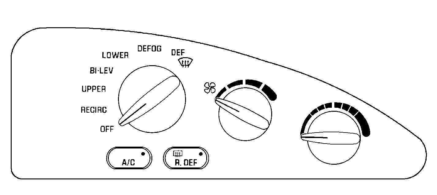
The heater and A/C control is the vehicle operator's
control point for the manual air conditioning system. The heater and A/C control
includes the following components:
| • | A rotary knob which selects the system operating modes. The following
items are the system operating modes: |
| • | A fan speed rotary knob |
Mode Selector Knob
The rotary mode selector knob on the heater and A/C control assembly
controls the following components:
| • | The 2 electrical switches |
The electrical switches activate the following components:
The vacuum valve supplies or vents the vacuum to the vacuum actuators.
The vacuum actuators determine the following conditions:
| • | The discharge locations |
By supplying vacuum to the actuators in various combinations, the vacuum
valve controls whether the air comes out of the following parts:
The vacuum valve also controls the following:
| • | Whether fresh (outside) air draws into the system |
| • | Whether inside air recirculates |
Temperature Control Knob
The rotary temperature control knob is a potentiometer which sends a
voltage signal to the A/C temperature valve actuator. The voltage signal varies
according to the temperature knob position.
When the temperature control knob moves fully to the left (COOL), less
than 1 volt is supplied to the A/C temperature valve actuator.
When the knob moves fully to the right (WARM), the battery voltage is
supplied to the A/C temperature valve actuator.
Fan Speed Control Knob
The fan speed control knob actuates the fan speed switch inside the
heater and A/C control. The fan switch position determines whether current
flows to the following components:
| • | The blower resistor assembly |
With the mode selector knob in any position but OFF, the following actions
occur:
| • | The fan circuit activates. |
| • | The fan operates at the speed selected. |
Control Assembly Description C67 Buick

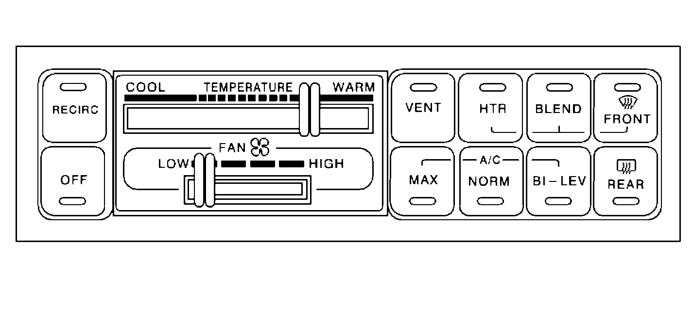
The electronic heater and A/C control assembly
is the vehicle operator's control point for the electronic air conditioning
system. The heater and A/C control includes the following components:
| • | Soft-touch buttons for the following system operating modes: |
| • | A temperature control lever |
| • | The ON/OFF switch located in the heater and A/C control for vehicles
equipped with a rear window defogger |
Operating mode buttons contain an LED indicator that illuminates when
selected. The rear window defogger button also contains an LED indicator.
The heater and A/C control is the electronic air conditioning systems
control center. The heater and A/C control sends commands to the system components
that control the following functions:
| • | A/C compressor operation |
| • | Air discharge temperature |
| • | Air discharge blower operation |
Control Assembly Description C61 Pontiac

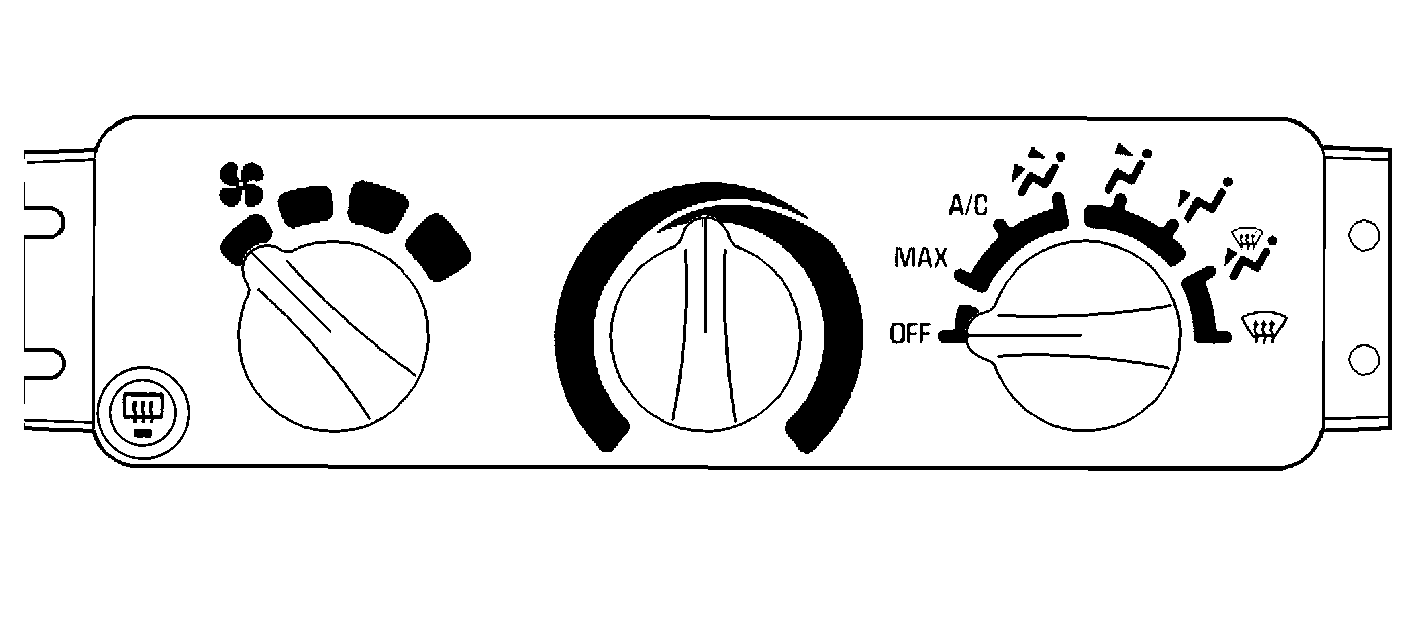
The heater and A/C control is the vehicle operator's
control point for the manual air conditioning system. The heater and A/C control
includes the following components:
| • | A rotary knob which selects the system operating modes. The following
items are the system operating modes: |
| • | A fan speed rotary knob |
Mode Selector Knob
The rotary mode selector knob on the heater and A/C control assembly
controls the following components:
| • | The 2 electrical switches |
The electrical switches activate the following components:
The vacuum valve supplies or vents the vacuum to the vacuum actuators.
The vacuum actuators determine the following conditions:
| • | The discharge locations |
By supplying vacuum to the actuators in various combinations, the vacuum
valve controls whether the air comes out of the following parts:
The vacuum valve also controls the following:
| • | Whether fresh (outside) air draws into the system |
| • | Whether inside air recirculates |
Temperature Control Knob
The rotary temperature control knob is a potentiometer which sends a
voltage signal to the A/C temperature valve actuator. The voltage signal varies
according to the temperature knob position.
When the temperature control knob moves fully to the left (COOL), less
than 1 volt is supplied to the A/C temperature valve actuator.
When the knob moves fully to the right (WARM), battery voltage is supplied
to the A/C temperature valve actuator.
Fan Speed Control Knob
The fan speed control knob actuates the fan speed switch inside the
heater and A/C control. The fan switch position determines whether current
flows to the following components:
| • | The blower resistor assembly |
With the mode selector knob in any position but OFF, the following actions
occur:
| • | The fan circuit activates. |
| • | The fan operates at the speed selected. |


