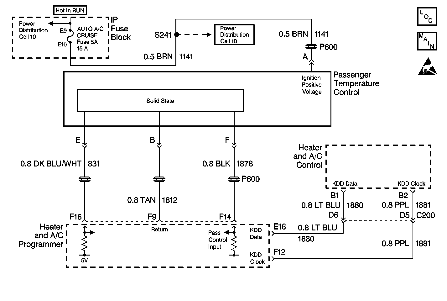
Circuit Description
The passenger temperature control assembly receives voltage signals from the HVAC programmer. The signal voltage will vary from 5 volts (open circuit) to 0 volts (short circuit).
Conditions for Setting the DTC
| • | The ignition is on. |
| • | The circuit is open or shorted. |
Action Taken When the DTC Sets
Code 034 is set.
Conditions for Clearing the DTC
| • | Using a Scan Tool . |
| • | A history DTC will clear after 40 consecutive IGN cycles have occurred without a malfunction. |
| • | HVAC programmer battery voltage is interrupted. |
Test Description
-
Determines if the passenger control assembly is operating properly.
-
Determines if the passenger control assembly is operating properly.
Step | Action | Value(s) | Yes | No |
|---|---|---|---|---|
1 |
Refer to Measuring Voltage in Wiring Systems. Does the voltage equal the specified value? | 5 V | Go to Step 12 | Go to Step 2 |
2 | Does the voltage measure greater than the specified value? | 5 V | Go to Step 3 | Go to Step 4 |
3 | Repair the short to the battery in CKT 831. Refer to Wiring Repairs in Wiring Systems. Is the repair complete? | -- | System OK | -- |
4 | Measure the voltage between passenger temperature control assembly harness connector terminal E and DLC terminal 4. Refer to Measuring Voltage in Wiring Systems. Does the voltage equal the specified value? | 5 V | Go to Step 5 | Go to Step 8 |
5 | Measure the voltage between HVAC programmer terminal E12 and terminal F9. Refer to Measuring Voltage in Wiring Systems. Does the voltage equal the specified value? | 12 V | Go to Step 6 | Go to Step 7 |
6 | Repair the open in CKT 1812. Refer to Wiring Repairs in Wiring Systems. Is the repair complete? | -- | System OK | -- |
7 |
Refer to Intermittents and Poor Connections Diagnosis in Wiring Systems. Is the repair complete? | -- | System OK | -- |
8 | Measure the voltage between HVAC programmer terminal F9 and terminal F16. Refer to Measuring Voltage in Wiring Systems. Does the voltage equal the specified value? | 5 V | Go to Step 9 | Go to Step 7 |
9 | Measure the voltage between passenger temperature control assembly harness connector terminal A and terminal E. Refer to Measuring Voltage in Wiring Systems. Does the voltage equal the specified value? | 12 V | Go to Step 10 | Go to Step 11 |
10 | Repair the short to ground in CKT 831. Refer to Wiring Repairs in Wiring Systems. Is the repair complete? | -- | System OK | -- |
11 | Repair the open in CKT 831. Refer to Wiring Repairs in Wiring Systems. Is the repair complete? | -- | System OK | -- |
12 |
Refer to Measuring Voltage in Wiring Systems. Does the voltage measure within the specified range? | 10-11 V | Go to Step 13 | Go to Step 14 |
13 | Replace the passenger temperature control assembly. Refer to Control Assembly Replacement - Passenger . Is the repair complete? | -- | System OK | -- |
14 | Does the voltage equal the specified value? | 12 V | Go to Step 15 | Go to Step 16 |
15 | Repair the short to the battery in CKT 1878. Refer to Wiring Repairs in Wiring Systems. Is the repair complete? | -- | System OK | -- |
16 |
Refer to Measuring Voltage in Wiring Systems. Does the voltage measure within the specified range? | 10-11 V | Go to Step 17 | Go to Step 7 |
17 | Repair the open in CKT 1878. Refer to Wiring Repairs in Wiring Systems. Is the repair complete? | -- | System OK | -- |
