Circuit Description
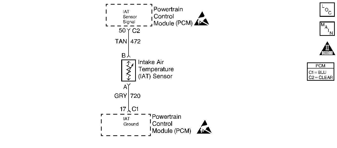
The Intake Air Temperature (IAT) sensor is a thermistor which measures the temperature of the air entering the engine. The PCM applies 5 volts through a pull-up resistor to the IAT sensor. When the intake air is cold, the sensor resistance is high and the PCM will monitor a high signal voltage on the IAT signal circuit. If the intake air is warm, the sensor resistance is lower causing the PCM to monitor a lower voltage. DTC P1111 will set when the PCM detects an intermittently high signal voltage on the intake air temperature sensor signal circuit.
Conditions for Setting the DTC
| • | No ECT sensor, MAF sensor or VSS DTC present. |
| • | The engine has been running for over 3 minutes. |
| • | Vehicle speed is less than 35 mph. |
| • | Mass Air Flow is less than 12 gm/s. |
| • | Engine Coolant Temperature is greater than 60°C (140°F). |
| • | IAT signal voltage intermittently indicates an intake air temperature less than -34°C (-29°F). |
Action Taken When the DTC Sets
| • | The PCM will not illuminate the malfunction indicator lamp (MIL). |
| • | The PCM will store conditions which were present when the DTC set as Failure Records data only. This information will not be stored as Freeze Frame data. |
Conditions for Clearing the MIL/DTC
| • | A History DTC will clear after 40 consecutive warm-up cycles have occurred without a malfunction. |
| • | The DTC can be cleared by using the scan tool Clear Info function. |
Diagnostic Aids
Check for the following conditions:
| • | Poor connection at PCM. Inspect harness connectors for backed out terminals, improper mating, broken locks, improperly formed or damaged terminals, and poor terminal to wire connection. |
| • | Damaged harness. Inspect the wiring harness for damage. If the harness appears to be OK, observe the IAT display on the scan tool while moving connectors and wiring harnesses related to the IAT sensor. A change in the IAT display will indicate the location of the fault. |
Reviewing the Fail Records vehicle mileage since the diagnostic test last failed may help determine how often the condition that caused the DTC to be set occurs. This may assist in diagnosing the condition.
Step | Action | Value(s) | Yes | No |
|---|---|---|---|---|
1 | Was the Powertrain OBD System Check performed? | -- | ||
2 | Select DTC info, Last Tst Fail and note any other DTCs set. Is DTC P0113 also set? | -- | Go to DTC P0113 Intake Air Temperature (IAT) Sensor Circuit High Voltage | |
3 | Is DTC P1106, P1115, and/or P1121 also set? | -- | ||
4 |
Was a problem found? | -- | ||
5 |
Was a problem found? | -- | ||
6 |
Was a problem found? | -- | ||
7 |
Was a problem found? | -- | ||
8 |
Was a problem found? | -- | ||
9 |
Was a problem found? | -- | Refer to Diagnostic Aids | |
10 |
Does scan tool indicate DTC P1111 failed? | -- | System OK |
