From the ignition control module, the PCM uses this signal to calculate
engine RPM and crankshaft position at engine speeds above 1200RPM. The PCM
also uses the pulses on this circuit to initiate injector pulses. If the
PCM receives no pulses on this circuit, DTC P1374 will set and the PCM
will use the 24X reference signal circuit for fuel and ignition control.
The engine will continue to start and run using the 24X reference signal
only.
From the ignition control module, the PCM uses this signal to calculate
engine RPM and crankshaft position at engine speeds below 1200RPM. The
PCM also uses the pulses on this circuit to initiate injector pulses. If
the PCM receives no pulses on this circuit, DTC P0336 will set and the
PCM will use the 3X reference signal circuit at all times for fuel and
ignition control. The engine will continue to start and run using the 3X
reference signal only.
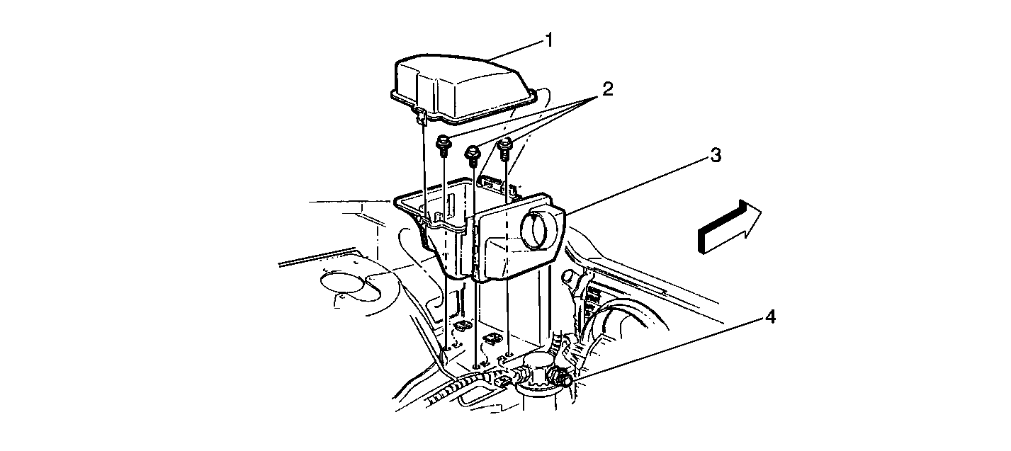
The A/C refrigerant pressure sensor (4) signal indicates high side
refrigerant pressure to the PCM. The PCM uses this information to adjust
the idle air control valve to compensate for the higher engine loads present
with high A/C refrigerant pressures and to control the cooling fans. A
fault in the A/C refrigerant pressure sensor signal will cause DTC P0530
to set. Refer to Heater, Ventilation, and Air Conditioning for a complete
description and on-vehicle service.
The A/C request signal indicates to the PCM that an A/C mode is selected
at the A/C control head. The PCM uses this information to adjust the idle
speed before turning ON the A/C clutch. If this signal is not available
to the PCM, the A/C compressor will be inoperative. For a complete description
of the PCM controlled portions of the A/C electrical system refer to PCM
Controlled Air Conditioning.
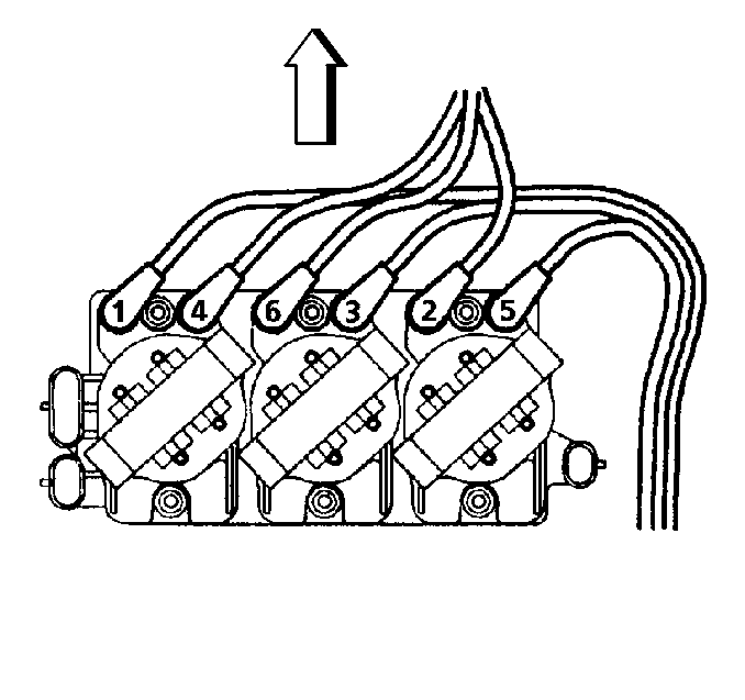
The 7X crankshaft position
sensor provides a signal used by the ignition control module to calculate
ignition sequence. The ignition control module also uses the crankshaft
position sensor signals to initiate 3X reference pulses which the PCM uses
as reference to calculate RPM and crankshaft position.
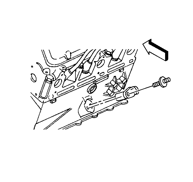
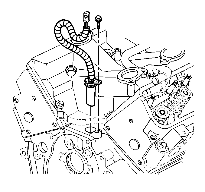
The camshaft position
sensor sends a cam signal to the PCM which uses it as a sync pulse to trigger
the injectors in proper sequence. The PCM uses the CAM signal to indicate
the position of the #1 piston during its intake stroke. This allows the
PCM to calculate true Sequential Fuel Injection (SFI) mode of operation.
If the PCM detects an incorrect CAM signal while the engine is running,
DTC P0341 will set.
If the CAM signal is lost while the engine is running, the fuel injection
system will shift to a calculated sequential fuel injection mode based on
the last fuel injection pulse, and the engine will continue to run. The
engine can be restarted and will run in the calculated sequential mode
as long as the fault is present with a 1 in 6 chance of injector sequence
being correct.
The PCM uses the serial
data line to communicate with various other components and systems within
the vehicle. If the PCM does not receive data from the Electronic Brake
and Traction Control Module (EBTCM), the PCM will store DTC P1573 indicating
loss of communication with the ABS/TCS system.
The PCM also receives rough road information from the EBTCM / EBCM
on the serial data circuit (CKT 800). The PCM uses the rough road information
to enhance the misfire diagnostic by detecting crankshaft speed variations
caused by driving on rough road surfaces. This allows false misfire information
to be rejected. The EBTCM / EBCM calculates rough road information by monitoring
the ABS wheel speed sensors. If a fault occurs which causes the PCM to
not receive rough road information while a misfire DTC is requesting the
MIL, DTC P1381 will set.
Under certain conditions, the PCM has the ability to request the EBTCM
to shut OFF the traction control via serial data (CKT 800). The following
DTCs will cause traction control to be disabled, an ABS/TCS DTC to be set,
and the Traction OFF lamp to be illuminated:
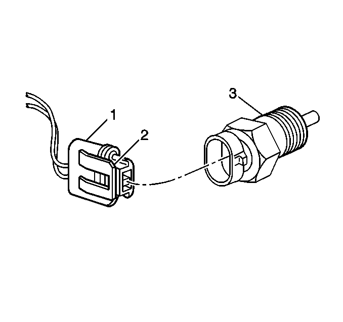
The engine coolant temperature
sensor (3) is a thermistor (a resistor which changes value based on
temperature) mounted in the engine coolant stream. Low coolant temperature
produces a high resistance (100,000ohms at -40°C/-40°F) while
high temperature causes low resistance (70ohms at 130°C/266°F).
The PCM supplies a 5 volt signal to the engine coolant temperature
sensor through a resistor in the PCM and measures the voltage. The voltage
will be high when the engine is cold, and low when the engine is hot. By
measuring the voltage, the PCM calculates the engine coolant temperature.
The scan tool displays engine coolant temperature in degrees. After engine
start-up, the temperature should rise steadily to about 90°C (194°F)
then stabilize when thermostat opens. If the engine has not been run for
several hours (overnight), the engine coolant temperature and intake air
temperature displays should be close to each other.
Engine coolant temperature affects most systems the PCM controls. A
hard fault in the engine coolant sensor circuit should set DTC P0117
or DTC P0118, an intermittent fault should set a DTC P1114
or P1115. The DTC Diagnostic Aids also contains a chart to check for sensor
resistance values relative to temperature.
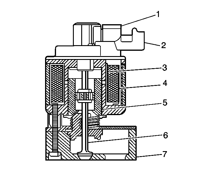
The PCM monitors the
EGR valve pintle position input to ensure that the valve responds properly
to commands from the PCM and to detect a fault if the pintle position sensor
and control circuits are open or shorted. If the PCM detects a pintle position
signal voltage outside the normal range of the pintle position sensor,
or a signal voltage that is not within a tolerance considered acceptable
for proper EGR system operation, the PCM will set DTC P1406.
