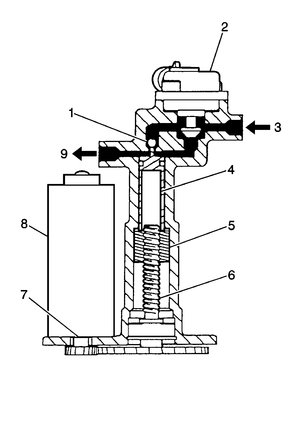
During TCS operation the ball screws and the pistons drive upward from
their home positions. The driving process seats the poppet valve which in
turn isolates the master cylinder. When the above conditions exist the brake
pressure to the wheel is a function of the controlled volume within the piston
chamber. Bi-directional motors drive the ball screws and the pistons. Driving
the ball screws and the pistons permits pressure to apply to, hold on, or
release from the wheels.
The base brakes and the ABS take precedence over the TCS under all conditions.
The TCS cannot be entered if the base brakes or the ABS are operating.
If the brake switch activates and calls for base brake operation or
ABS operation during TCS operation, the TCS modulator assembly will automatically
return the TCS ball screws and the pistons to their home positions.
The applied brake pressure from the master cylinder can overcome the
poppet valve spring. Overcoming the poppet valve spring applies brake pressure
to the wheels immediately, while the TCS ball screws and pistons return to
their home positions.
The PCM uses the above controls in order to reduce engine torque. The
reduction in torque limits slippage of the drive wheels during acceleration.
The temperature of the brake lining may rise to a high temperature during
prolonged TCS operation. Excessive temperatures may increase the rate at which
the lining wears. The TCS system includes a brake thermal model. The brake
thermal model estimates the brake temperatures during braking and TCS operation
in order to prevent excessive brake lining wear.
The TCS does not normally disable during a traction event. It will disable,
however, if the TCS reaches the maximum temperature threshold.
The operator of the vehicle can turn the TCS off and on with a momentary
switch. The TCS switch is located on the instrumental panel and is identified
as TCS.

