Tools Required
J 39400-A Halogen Leak Detector
Removal Procedure
- Remove the air cleaner assembly. Refer to Air Cleaner Assembly Replacement in Engine Controls-3.4L.
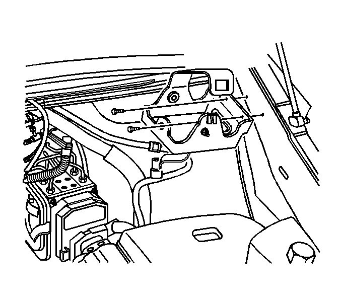
- Disconnect the cruise control module electrical connector.
- Remove cruise control module from the mounting bracket and reposition aside.
- Remove the cruise control module mounting bracket bolts.
- Remove the cruise control module mounting bracket.
- Recover the refrigerant from the A/C system. Refer to Refrigerant Recovery and Recharging .
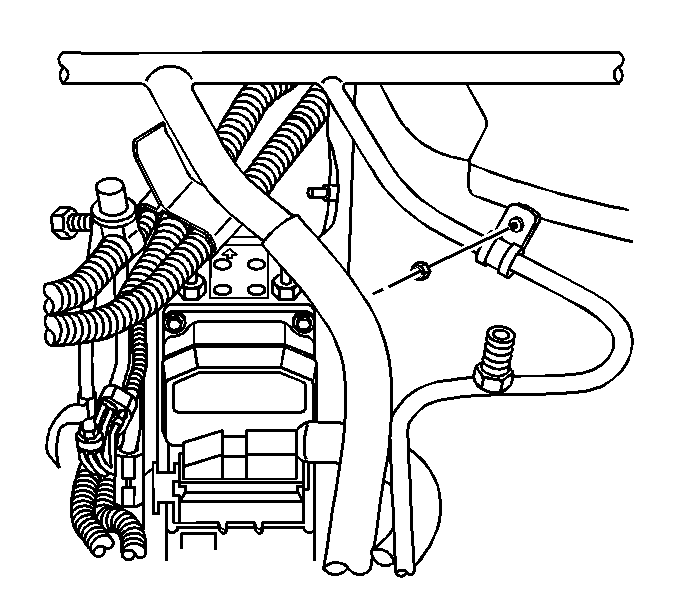
- Remove the evaporator inlet tube clamp nut.
- Remove the wiper module cover. Refer to Wiper Module Cover Replacement in Body and Accessories.
- Remove the left wiper arm linkage nuts.
- Disconnect the electrical connector from the A/C refrigerant pressure sensor.
- Remove the A/C refrigerant pressure sensor from the evaporator inlet tube.
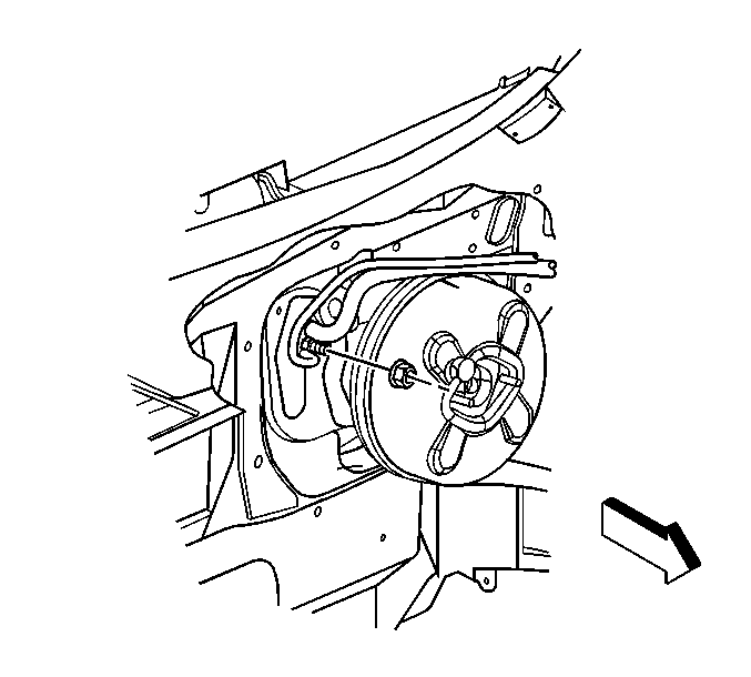
- Disconnect the vacuum hose from the brake booster and reposition.
- Remove the evaporator outlet tube nut at the TXV.
- Disconnect the evaporator outlet tube and evaporator inlet tube from the TXV.
- Disconnect the evaporator inlet tube from the evaporator outlet tube.
- Cap or tape the TXV.
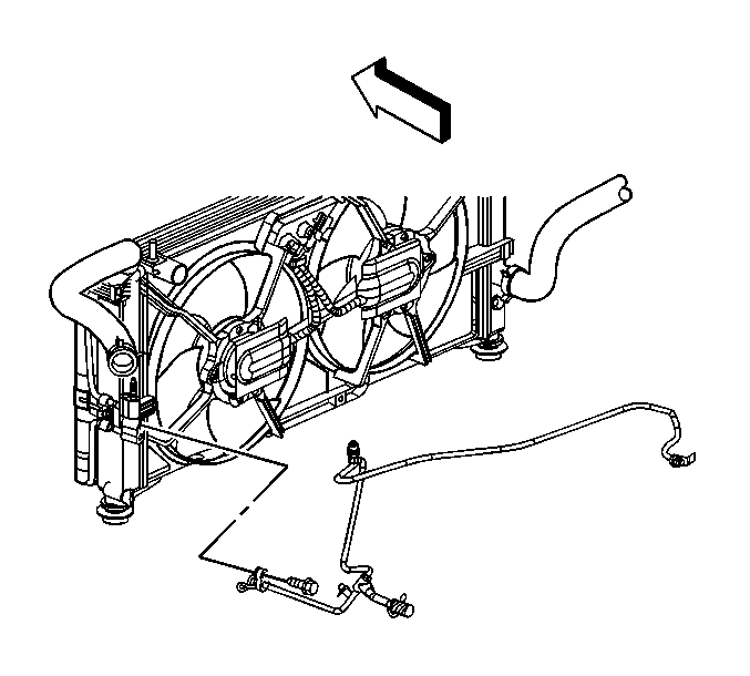
- Remove the evaporator inlet tube to condenser fitting bolt.
- Disconnect the evaporator inlet tube from the condenser.
- Cap or tape the condenser.
- Disconnect the auxiliary evaporator inlet tube from the evaporator inlet tube.
- Cap or tape the auxiliary evaporator inlet tube.
- Remove the evaporator outlet tube bracket bolt.
- Disconnect the electrical connector on the evaporator outlet tube bracket.
- Remove the evaporator inlet tube.
- Remove and discard the sealing washers and O-ring.


Reposition the left wiper arm linkage for access.

Important: Cap or tape the open A/C refrigerant tube and A/C refrigerant components to prevent system contamination.
Important: Gently lift up on the evaporator outlet tube bracket to allow enough clearance to slide the evaporator inlet tube underneath.

Installation Procedure
- Install the new O-ring. Refer to O-Ring Replacement .
- Install new sealing washers onto the evaporator inlet tube. Refer to Sealing Washer Replacement .
- Install the evaporator inlet tube.
- Connect the electrical connector on the evaporator outlet tube bracket.
- Install the evaporator outlet tube bracket bolt.
- Remove the cap or tape from the auxiliary evaporator inlet tube.
- Connect the auxiliary evaporator inlet tube to the evaporator inlet tube.
- Remove the cap or tape from the condenser.
- Connect the evaporator inlet tube to the condenser.
- Install the evaporator inlet tube to condenser fitting bolt.
- Remove the cap or tape from the TXV.
- Connect the evaporator inlet tube to the evaporator outlet tube.
- Connect the evaporator inlet and outlet tubes to the TXV.
- Install the evaporator outlet tube to TXV nut.
- Install the evaporator inlet tube clamp nut.
- Install the A/C refrigerant pressure sensor to the evaporator inlet tube.
- Connect the A/C refrigerant pressure sensor electrical connector.
- Connect the vacuum hose to the brake booster.
- Install the left wiper arm linkage.
- Install the left wiper arm linkage nuts.
- Install the wiper module cover. Refer to Wiper Module Cover Replacement in Body and Accessories.
- Install the cruise control module mounting bracket.
- Install the cruise control module into the mounting bracket.
- Connect the cruise control module electrical connector.
- Evacuate and recharge the A/C system. Refer to Refrigerant Recovery and Recharging .
- Leak test the fittings of the component using J 39400-A .
- Install the air cleaner assembly. Refer to Air Cleaner Assembly Replacement in Engine Controls -3.4L.
Important: Gently lift up on the evaporator outlet tube bracket to allow enough clearance to slide the evaporator inlet tube underneath.

Notice: Use the correct fastener in the correct location. Replacement fasteners must be the correct part number for that application. Fasteners requiring replacement or fasteners requiring the use of thread locking compound or sealant are identified in the service procedure. Do not use paints, lubricants, or corrosion inhibitors on fasteners or fastener joint surfaces unless specified. These coatings affect fastener torque and joint clamping force and may damage the fastener. Use the correct tightening sequence and specifications when installing fasteners in order to avoid damage to parts and systems.
Tighten
Tighten the bolt to 5.5 N·m (48.7 lb in).
Tighten
Tighten the nut to 27 N·m (20 lb ft).
Tighten
Tighten the bolt to 16 N·m (12 lb ft).

Tighten
Tighten the nut to 16 N·m (12 lb ft).

Tighten
Tighten the nut to 3.3 N·m (29 lb in).
Tighten
Tighten the sensor to 5 N·m (44 lb in).
Tighten
Tighten the nuts to 5 N·m (44 lb in).

Tighten
Tighten the bolts to 6 N·m (53 lb in).
